Off-Grid Solar Power Simplified


~


RVs, Vans, Cabins, Boats, and Tiny Homes

Introduction

Electrical Units

Voltage

Current

Resistance

Power

Watt-hour

Amp-hour

Energy Measuring Equipment

Digital Meter

Ammeter or Clamp Meter

Basic Formulas

Ohms Law

Power

Energy or Watt-hours

Energy Cost

Amp-hours

Volt-Ampere

AC and DC

Difference Between AC and DC

AC and DC in the System

Tools

Wire Stripper

Cable Stripper

Lug Crimping Tool

Hammer Lug Crimper

Wire Crimping Tool

Conduit Cutter

Screwdrivers

Needle Nose Pliers

Wire Cutters

Cable Cutter

Hex Nut Ratchet Set

Torpedo Level

Hole Saw

Cordless Drill

Drill Bits

Safety Goggles

Equipment

Wire Lugs

Crimp Connectors

MC4 connectors

Busbar

Displays

Cable Gland

Combiner box

Fuses and Circuit Breakers

DC Isolator Switch

Basic Circuitry

Basic Light Circuit

Short Circuit

Load Types

Resistive Loads

Inductive Type Loads

Sizing your Solar System

12, 24, and 48V systems

Calculations

Wiring

Wire core material

Sizing Factors

Wire Types

Calculating Wire Sizes

Wire Safety

Batteries

How do Batteries Work?

Lead-Acid

Alkaline Batteries

Lithium Batteries

Lead-Acid vs. Lithium

Temperature and Lead-Acid Batteries

Using car Batteries

Series and Parallel

C-rate

Battery Monitors

Sulfation

Over-Discharging

Overcharging

State of Charge

Depth of Discharge

Maximum Cycles

National Electrical Code

Maintenance of Batteries

Buying Used Batteries

Weight of Batteries

Shunt

Solar Panels

Types of Panels

Conversion Efficiency

I-V Curve

P-V Curve

STC and NOCT

Effect of Insolation and Temperature

Ambient Temperature and Cell Temperature

Temperature Effects on Efficiency

Series and Parallel Connections

Azimuth

Tilt Angle

Shading

Hotspots

Blocking Diodes

Fusing Solar Panels

Seasons and Solar Map

Placement of panels

Mounting Panels

Cleaning Panels

Solar Panel Lifespan

Panel Voltage

Buying Used Solar Panels

Charge Controller

What is the Task of a Charge Controller?

Different Charge Controllers

PWM or MPPT?

Selecting a Charge Controller

Temperature Compensation

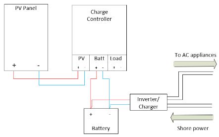
Connecting the Charge Controller

Multiple Charge Controllers


Inverters

What is the Task of an Inverter?

Types of Inverters

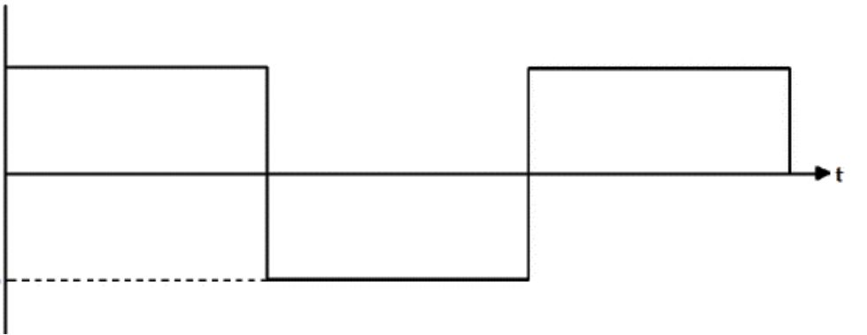
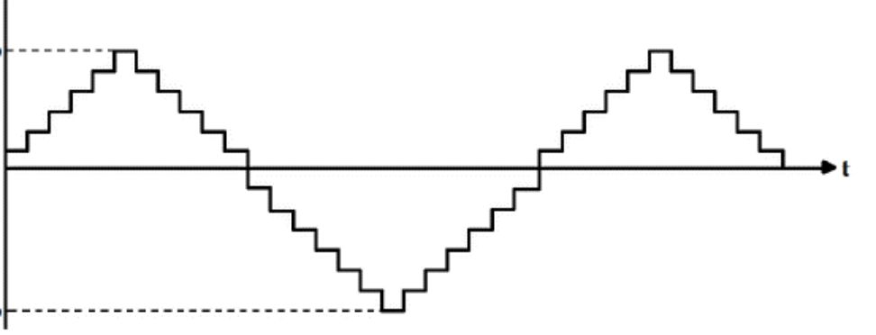
Inverters Output Signal

Utility Interactive for on-grid Connections

Efficiency

Automatic Load Shedding

Low Voltage Disconnect

Peak Power

Power Consumption

Parallel Inverters

Charging from Alternator

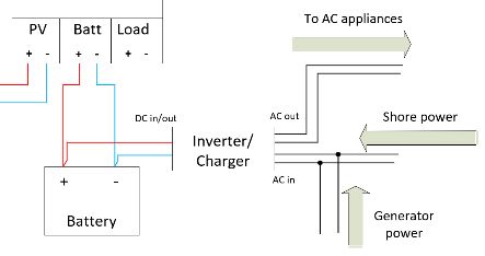
Charge from Generator

Grounding

DIY Solar Power Setup

Solar System Examples

12V 500W inverter with 400W of solar

24V 1kW inverter with 800W of solar

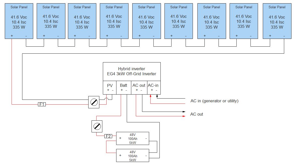
48V 3kW inverter with 3kW of solar

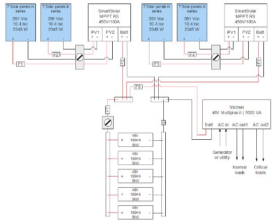
48V 5kW inverter 9kW of solar

Recommended Brands

Conclusion

Copyright 2020-2022 by cleversolarpower.com - All rights reserved.


The transmission, duplication, or reproduction of any of the following work, including specific information, will be considered an illegal act irrespective of if it is done electronically or in print. This extends to creating a secondary or tertiary copy of the work or a recorded copy and is only allowed with an expressed written consent from the Publisher. All additional rights reserved.


Additionally, the information in the following pages is intended only for informational purposes and should thus be thought of as universal. As befitting its nature, it is presented without assurance regarding its prolonged validity or interim quality. Trademarks that are mentioned are done without written consent and can in no way be considered an endorsement from the trademark holder.


Introduction

To get access to color pictures and schematics in this book, visit my website at: https://cleversolarpower.com/offgridsolarbook

This page is exclusively for people who bought the book. Use the password which is written on the last page of this book.


This book focuses on the practical approach to designing and installing an off-grid solar power system.


This book will start by discussing the basics of an off-grid system. This will include understanding the electrical units, measuring electricity, formulas, and the difference between AC and DC.


Next, we will discuss the different tools you need to build your system. This chapter is followed by a list of equipment that you will need. This list will save you many trips to the hardware store. The chapter also provides more detail about different fuses and where to put them.


From there, we dive into some circuitry and load types. The following chapter is the most practical because we will calculate how big your system needs to be.


After you know how to size your system, we go more in-depth on choosing types of wire and wire sizes. This is a crucial step that cannot be overlooked.


Then we discuss the batteries, solar panels, charge controllers, and the different kinds of inverters.


We will then discuss grounding and take you step by step in making your own solar system.

Lastly we give you some inspiration and schematics for four different designs with an explanation of fuse and wire sizes.


We end the book by recommending a list of quality brands for you to choose from.


This book is geared towards beginners and intermediate users and can be heavy on formulas. Don’t let these intimidate you. They are easy to implement if you follow the step-by-step guidelines described in this book. Let’s get started with the basic electrical units.

Electrical Units

Energy can be described in many ways, but basically, energy is referred to as the capacity of developing a specific work. Energy is presented in many ways in nature, and one of them is electricity, which is described as the capacity to establish electrical work.


To understand how electricity works, some important concepts must be addressed.


First, you must understand that an electrical circuit can be described as the interconnection of electrical components where at least three basic elements will exist:


  • A power source
  • A conductor
  • A load

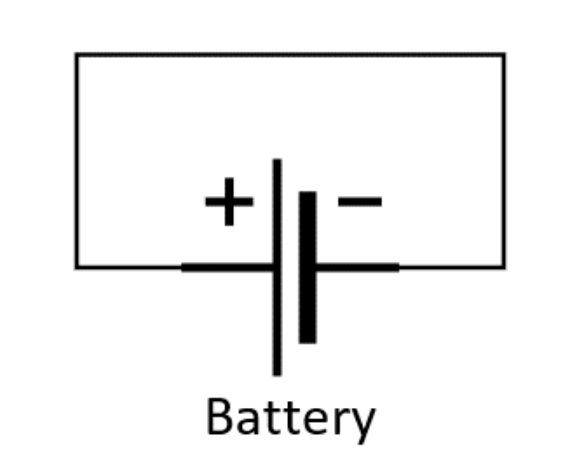
Basic electrical circuit


The power source is the element that produces or stores electricity (a battery, a generator, or a solar panel).

The conductor is the element through which electricity flows.

The load is the element that receives electricity for performing work (a lamp generates light, a motor provides motion, and an electrical resistor creates heat).


To understand the concepts used throughout this book, we need to describe some electrical terms first.

Voltage

Electricity is generated by the movement of electrical charges (electrons). In order to move an electron from one point to the other, it is necessary to perform electrical work.


This work is performed by an electromotive force (EMF) or voltage generated by the power source. Voltage can be understood as the pressure required to move the electrons from one point (A) to a second point (B) within an electrical circuit. The greater the voltage, the greater the flow of electrons through an electrical conductor.


This movement is generated from the highest electrical potential point (A) to the lower electrical potential point (B). Voltage is referred to as the electrical potential difference between these two points.


Voltage is measured in Volts (V).

Current

The second important electrical unit is current.


The electrical current can simply be understood as the intensity of the flow of electrons per second through a conductor.


This element is measured in Amps (A) or (I).

Resistance

The resistance is referred to the opposition of a specific material to the flow of electrical current. In other words, the resistance provides a reference of how easy or how hard it is for the electrons to flow through any material (steel, aluminum, copper, etc.).


Every electrical load or conductor has an internal resistance, which is measured in ohms (Ω). For example, wood has a higher electrical resistance than copper.

Power

Power is one of the most important variables in electricity as it represents the combination of voltage and current in an electrical circuit.


For an electrical load to perform any type of work (illumination, motion, heat), this element demands an instantaneous equivalent work source, which is provided by power. Power acts as a reference to the rate at which electricity is delivered (power source) or consumed (load) and is the product between voltage and current. The unit of power is Watt (W).

Watt-hour

As we mentioned before, power is the instantaneous rate at which electricity is provided or consumed. When we refer to energy, we are evaluating how electricity is being delivered or consumed over time.


In other words, electrical energy is described as the power generated or consumed over time.


As a general convention, electrical energy is expressed in watt-hour (Wh). Representing the consumption of a specific number of watts in a single hour. This unit will generally be used to account for the energy consumption of electrical loads in an off-grid solar power system.


Also, when consumption is higher, it is generally expressed in kilowatt-hours (kWh), which is the consumption of 1,000 watts of power in a single hour. You will be already familiar with the term Kilo Watt-hours, as it is listed on your electricity bill.

Amp-hour

Energy can also be expressed as consumption of the amount of current in a single hour and is referred to as Amp-hour (Ah).


Amp-hour is used to describe the amount of energy a battery can store at the nominal voltage. The battery of a typical smartphone has a capacity of 3 Amp-hours or 3,000 milli Amp-hours.


It’s helpful to know that Ah doesn’t say anything about the capacity of a battery. You need to know the voltage to know the total amount of watt-hours.

Energy Measuring Equipment

Digital Meter

The digital meter (also known as a digital multimeter) is a test tool that is used to measure at least three variables:


  • Voltage (AC and DC)
  • Electrical current (DC)
  • Resistance


A digital meter combines the capabilities of three tools into one: an analog voltmeter (measures volts), an analog ammeter (measures amps), and an analog ohmmeter (measures resistance).


Image result for digital multimeter

Typical digital meter


Every digital meter should have:


  • A display to show measured values.
  • A rotary switch to change variables.
  • Input jacks for test leads.

The meter will have a range of unit scale measurements from millivolts (mV) to volts (V), from milliamps (mA) to Amps (A), and from milliohms(mΩ) to mega-ohms (MΩ).


You will need to know the unit's range that you will be testing to select the correct scale and obtain an accurate result.


Generally, we will use voltage, ohms, and sometimes amps for solar power applications.


Keep in mind that you will have test leads with insulated wires to test the electrical circuits. There will be a test lead for positive (red) and a test lead for negative (black). When measuring DC circuits, the colors (polarity) of the wires matter. It does not matter in AC because it is alternating. More on this later.


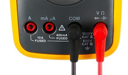
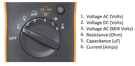
You need to put the black lead in the ‘COM’ input and the red lead in the ‘V’ input when you test voltage. Then you need to select the ‘V’ variable on the rotary switch and place the positive and negative leads accordingly to obtain an accurate measurement. Otherwise, you will get a negative value.


Input leads of a multimeter (left: black, right: red)


The same concept applies to measuring resistance. The black lead must go in the ‘COM’ input, and the red lead should be in the ‘Ω’ input, which is the same as the ‘V’ input. Select the Ω symbol on the rotary switch to measure the resistance of a device.


When testing voltage, you must measure it in an open circuit, which means measuring without load. For example, if you wish to measure the voltage that comes out of your power socket, you touch both pins' positive and negative to the electrical wires.


If you want to measure resistance, you must measure it without any applied voltage. For example, if you're going to check if a fuse is broken, you take out the fuse and measure at both ends of the fuse. If the display states a resistance of 1 or higher, the fuse is broken. Resistance is measured in an open circuit.


Although you could measure current using a digital meter, it’s better to use an ammeter for this. This is because current will flow through your meter, potentially damaging or blowing a fuse inside if no load is applied. Most meters will be limited to 10Amps, which is not a lot. There is no need to measure current because you can calculate it using the formulas discussed in the next chapter.


The layout of a Fluke digital multimeter


Read the digital multimeter manual for further information on measuring voltage, resistance, and current.

Ammeter or Clamp Meter

The digital ammeter or clamp meter is a device that combines the advantages of a digital multimeter with an additional feature.


Like the digital multimeter, the ammeter can measure voltage (DC and AC), resistance, continuity, AC current, and other variables such as frequency, temperature, or capacitance.


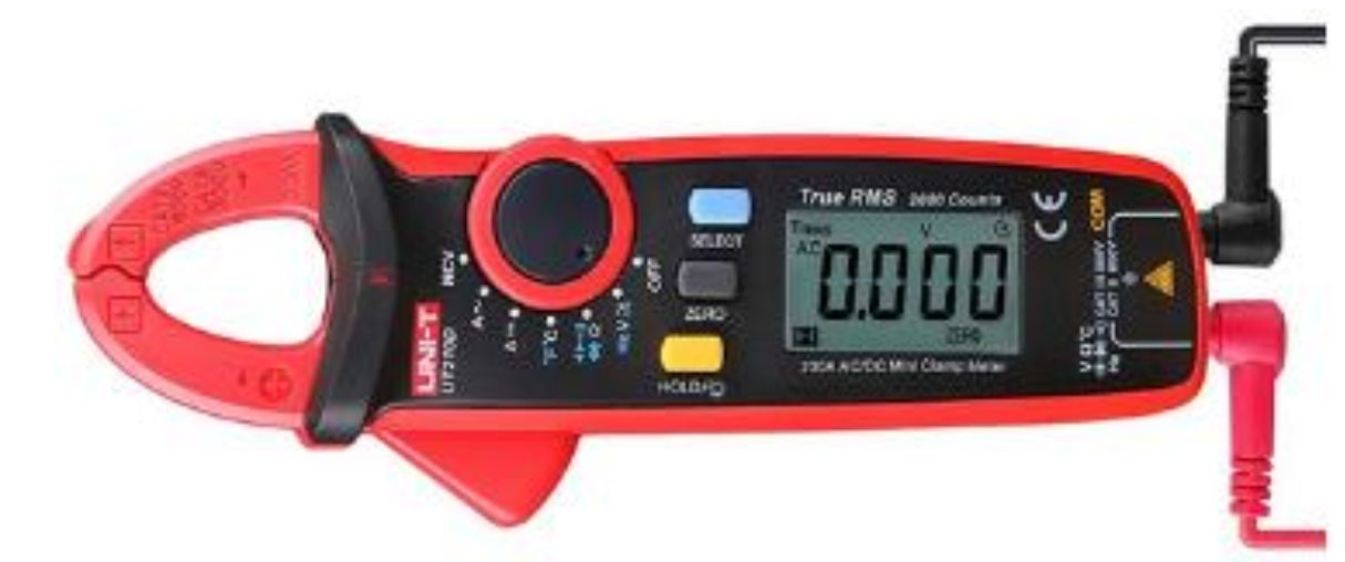
The main difference with the multimeter is that the ammeter includes a clamp that allows you to measure the RMS (root mean square) value of the electrical current. You simply need to open the clamps and close them around a conductor through which an electrical current is flowing. You cannot measure a cable with a positive and negative wire inside it. It can only measure one wire at a time because they will cancel each other out.


A cheaper ammeter can only measure AC current, but not DC current. When you buy one, make sure it can measure DC current. Check the Amp rating to make sure it can read at least 100Amps (depending on your system).


Clamp meter by UNI-T

Basic Formulas

To perform calculations related to sizing an off-grid PV system, you need to use some basic formulas.

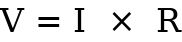
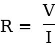
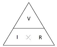
Ohms Law

Where,


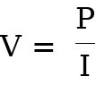
V = Voltage (Volts), sometimes written as ‘U’

I = Electrical Current (Amps)

R = Resistance (Ohms)


Or,


Or,


Using a triangle for the formulas is an easy way to remember them. Once you remember the position of the units in the triangle, using these formulas becomes easy.

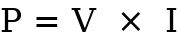
Power

Where,


P = Power (Watts)

V= Voltage (Voltage), sometimes written as ‘U’

I = Electrical Current (Amps)


Or,

Or,


Energy or Watt-hours

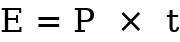
Where,


E = Energy (Watt-hours)

P = Power (Watts)

t = Time (hours)

Your electrical company uses this unit to bill your energy consumption. Watt-hour is a large number. Therefore, kilowatt-hour is used. This means that 1,000 Watt-hours is equal to 1-kilowatt-hour or simply 1 kWh.


Running a heater with a power rating of 1,000 Watts for one hour will consume 1,000 Watt-hours of energy or 1 kWh.


Let’s explore why voltage is an important factor when calculating Watt-hours.


Let’s take two batteries for example.


  • Battery one has a capacity of 2 Amp-hours at 1.2 Volts.
  • Battery two has a capacity of 2 Amp-hours at 12 Volts.

It seems that these batteries have the same amount of stored energy because the amp-hours are the same. However, this is not true because the voltage is different. Let’s calculate the number of watt-hours stored in each of these batteries.


We can see that the stored energy in battery two is higher. That is why Amp-hours alone is not a clear indication of the available energy in a battery. Watt-hours is the correct unit.

Energy Cost

Every state or country has different rates for electricity. To know how much you need to pay your electricity provider, you need to know your local electricity rate. The national average in the U.S. is $0.12 per kilowatt-hour. Note that the unit is per kilowatt-hour and not per watt-hour.


If you run a light that has a power rating of 20 Watts and run it for 8 hours each day for 30 days, this is how much you will need to pay your electrical provider:


Amp-hours

One Amp-hour is equivalent to one amp expended for one hour.


Amp-hours are not commonly used in standard electrical practice but indicate a battery's capacity.


For example, a simple AA battery has a capacity of 2,000mAh (milliamp hours) or 2Ah. This means the battery can theoretically supply a load of two amps for one hour. It could also deliver one amp for two hours, and so on.

If you have a bigger battery with 100Ah of capacity, you can draw 100 Amps for one hour or 10 Amps for 10 hours.


This is only in theory because different batteries have different depths of discharge and charge/discharge rates. We will talk more about this in the battery chapter.

Volt-Ampere

Volt-Ampere, also called VA, is the unit for apparent power. Some inverters list the VA value instead of the power (watts) value. Volt-Ampere and Power in DC systems are the same.


Volt-ampere becomes different when we transfer DC into AC and connect an inductive or capacitive load.


Most of your loads will be inductive, for example, AC pumps or fans. You have to calculate the true power draw with the power factor of the specific device you want to power.


Let’s say you want to power a pump of 800 watts with a power factor of 0.8. Then we apply the formula:


We would need an inverter that is capable of handling a load of 1000VA.


We can also calculate it in reverse:


You can see that the Volt-Ampere rating is always higher than the true power rating. If you buy an inverter and attach inductive loads to it, you have to be wary about this. If manufacturers state the inverter power in VA, you must multiply this number by 0,8 to have a more accurate power rating.

AC and DC

Difference Between AC and DC

In a solar power system, you will most likely have two signals:


  • DC – Direct current
  • AC – Alternating current

Therefore, you must understand the differences between these signals to know which device you must use, where, and why.


Simply put, DC stands for Direct Current, and AC stands for Alternating Current. The direct current is an electrical signal that constantly flows in a single direction across the electrical circuit over time.


Related image

AC and DC symbols


You can see a DC voltage signal in the following image, which is stable and always has a constant value. However, values in other cases may increase or decrease over time.


DC Voltage Signal

Source: LWClearning


The most important factor in qualifying as a DC signal is that the wave is either entirely positive or entirely negative (always above or below the X-axis).


The best example for DC power source signals is a battery. Any battery provides a constant DC voltage (generally between 2V and 12V), while the electrical current may increase, decrease, or stay constant over time, depending on demand.


The solar panel is also a DC power source. When testing voltage and current for this component, you must use DC measurement instruments.


If you measure DC voltage with a digital meter, you will get a positive (+) or negative (-) reading. This way, you can figure out the polarity of a DC source. Try it with a battery and see if you can figure out the polarities without looking at the positive and negative signs. Use your multimeter to double-check your solar panels' polarity before connecting them to your charge controller.


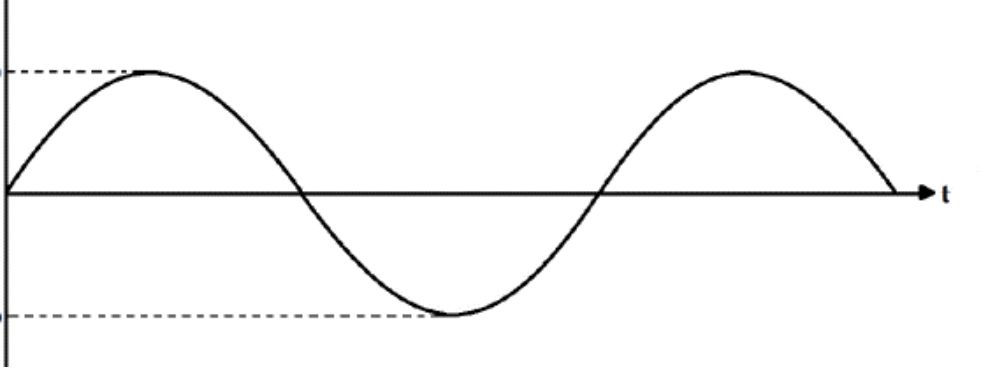
On the other hand, AC is entirely different. In this case, the electrical signal fluctuates. The signal changes between positive and negative values periodically over time. This is what we call a sine wave.


AC power signal and one period


This alternating shape is created by a synchronous generator, which uses mechanical energy (derived from the movement of a turbine driven by water or steam) and converts it into a periodic electrical signal output.


This generator has a rotor that spins around its axis in 360 mechanical degrees. The output signal always features 360 electrical degrees. These changes in the value of the AC signal are referred to as the period of the wave, which at the same time is referred to as the frequency of the signal.


Another method of creating an AC signal from a DC source is to use electronics which we will discuss in the chapter ‘inverters’. Most countries around the world use frequencies of 50 Hertz. The U.S., Canada, and several other countries use 60 Hertz. It means that the electricity completes 60 periods in one second.


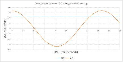
In the following image, you can see DC and AC voltage in the same graph. The wave is the AC signal, while the flat line is a DC signal.


https://media.licdn.com/dms/image/C4E12AQF7Um_hoLdkWw/article-inline_image-shrink_1500_2232/0?e=1568246400&v=beta&t=s23gWGP9dM2ao1R8IJKSYt_a6f3xdeDfrkYIqGnqYz4

DC and AC Voltage Curves

Source: Zoroad Electric


Now, you may be wondering how you can measure the value of the AC signal when it’s constantly changing.


The measuring instruments for AC signals will display a specific value called the Root Mean Square (RMS) value. If you measure with a digital meter, you will always measure the Root Mean Square unless specified otherwise.


The RMS is a constant value of the AC signal equal to the value of the direct current that would produce the same average dissipated power in a resistive load.


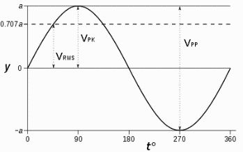
In the following figure, you can see the position of the RMS in an AC voltage signal.


V RMS value of a voltage signal

Source: Wikipedia


The peak (VPK) of a sine wave in the U.S. measures 170 Volts AC, but you will see 120 Volts AC (VRMS) on your measuring device. Or,


The power grid works using an AC signal that reaches the residential, commercial, and industrial sectors under particular specs related to quality, voltages, and ancillary services.


At the residential level, there may be three possible types of RMS values for the AC voltage:


  • 120V single phase
  • 120/240V split phase
  • 208V three-phase


Most countries use different power grids. In Europe, for example, the power grid is different. You will find these values:


  • 230V Single-phase
  • 400V Three-phase
  • 690V Three-phase

AC and DC in the System

You will most likely have both AC and DC signals in a solar power system. The solar panels, the batteries, and the charge controller will always work in DC. The inverter will transform the DC signal from the battery into an AC signal to power specific loads.


Therefore, when you test voltage or current in any part of the electrical circuit located before the inverter, you will have to measure in DC. If you test any variable in a section located after the inverter, you will measure AC.


Simplified graphic of DC and AC in the solar PV system

Tools

Wire Stripper

A wire stripper is a multi-use tool necessary for any electrical installation. It allows you to strip and cut any wire with gauges between 10-24AWG. The device will allow you to easily cut either copper or aluminum wires with precision without damaging the metal part of the electrical wire.


Wire stripper

Cable Stripper

A cable stripper is also needed to strip cables from #5AWG to 4/0AWG, which a wire stripper cannot do. The cable stripper can cut PVC, rubber, foamed polyethylene (PE), and other insulating materials.

The interesting and more useful fact about this tool is that you can make longitudinal, circular, spiral, and mid-span cuts to remove the cable's jacket. The device includes a cable holder that makes the cutting process easier.


You can adjust it easily to the gauge of the cable. The cutting is made through a blade depth knob that adjusts the blade (which is also replaceable) to fit the size of the cable.


Always calibrate the tool on a wire end to ensure the blade doesn’t cut the wire strands.


Cable stripper

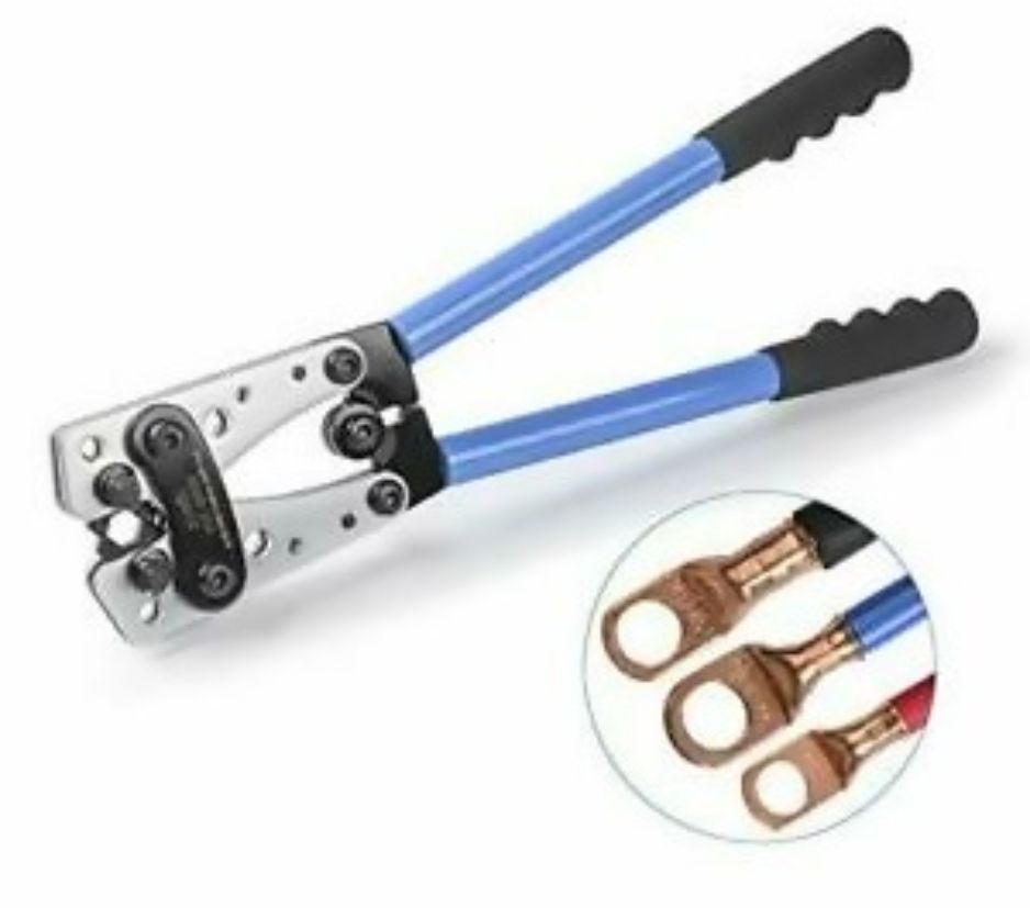
Lug Crimping Tool

This product is intended for installations where battery banks are used. The product can crimp battery cable lugs with standard sizes between #8AWG and 1/0AWG.


The stripping of the cable to introduce the lug should be done with a cable stripper

Image result for wire lugs for batteries

Lug crimping tool


Crimping lugs is a crucial operation in your solar system. Therefore it’s recommended to buy pre-crimped wires crimped by a machine. If you are crimping many wires, getting this tool might be a better option. I recommend that you don’t crimp wires larger than 4AWG or 25mm² (100amps). If you need larger wires, you need a professional hydraulic crimper.

Hammer Lug Crimper

Another option for the same purpose is a hammer lug. It’s a more economical solution to crimp the cable lugs for your battery bank or inverter.


I don’t recommend this tool for gauges larger than #6AWG or 16mm². If you crimp anything larger, use a lug crimping tool, or buy pre-crimped cables.


Hammer lug crimping tool

Wire Crimping Tool

This tool is suitable for crimping individual wires. It integrates a ratcheting mechanism with an adjustable clamping force that is useful for precise and repeatable crimps and adds more crimping power into each squeeze.


Its ratcheting mechanism lets you secure a wire connector before inserting the stripped wire into the lug. You will be able to crimp wire terminals for gauge sizes between 22 and 10AWG (0.5-6mm²) split into three crimping options marked by red, blue, and yellow, indicating the gauge ranges for each purpose.


Crimping tool

Conduit Cutter

The following tool on our list is the conduit cutter. Conduit is generally used in electrical installations to protect cables or wires from water and physical damage.


However, for the conduit to fit your wiring installation, you must cut it to adjust the length properly. For this purpose, a conduit cutter tool is needed.


The conduit cutter is used for multiple applications like cutting PVC pipe or PEX pipe. It is also suitable for cutting CPVC, PP, and PE-XB pipes that will allow you to cut them within a few seconds.

PVC conduit cutter

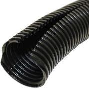
It is recommended to use flexible polyethylene pipe if you have a vehicle. It will protect the wires from vibration. It will also act as a cable highway, which is helpful if you want to add an extra wire from the vehicle's back to the front.

Screwdrivers

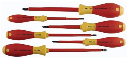
Screwdrivers are needed in almost any installation. However, for electrical installations, using an insulated screwdriver is preferred.


For this purpose, purchasing a screwdriver set with six pieces tested to resist up to 1,000 Volts AC or 1,500 Volts DC is the best choice. Each tool will be covered with a non-conductive material that can reach such a rating, making it safe for electrical installations.


Besides, a soft handle with an outer cushion grip allows you to add 40% more torque than traditional plastic handles.


Electrical screwdrivers

Needle Nose Pliers

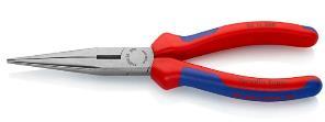
The needle nose pliers are the perfect tool to bend wires. Their half-round tapered jaws are longer and narrower, useful for places other pliers cannot reach.


These pliers come with a cutting tool but are generally not used for that purpose. The needle plier can usually be found in three handle styles: plastic coated handles, comfort grip handles, and the 1000V insulated handle that meets IEC standards, which is the model for electrical installations.

Needle nose pliers

Wire Cutters

The wire cutter is another valuable tool to cut individual wires. The device is integrated with machined jaws to provide the maximum gripping strength and has been designed with an induction hardened cutting edge that stays sharper for longer.


Normal wire cutter


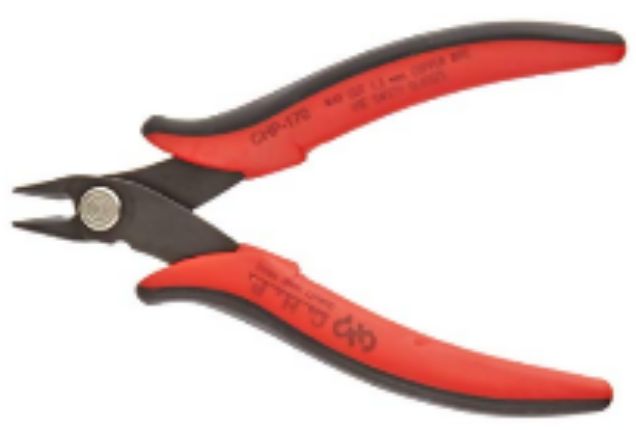
Another valuable tool is a flush cutter. This tool will have a 21-degree angle for flush-cutting, and its heat-treated carbon steel construction can provide durability and long-life performance. The small size makes it easy to carry around. 


Small wire cutter or flush cutter

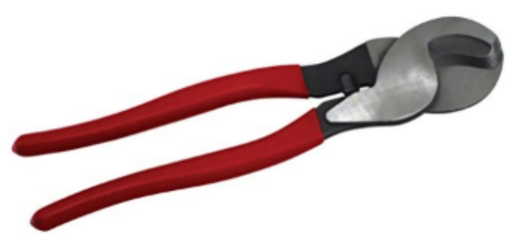
Cable Cutter

There may be occasions where the wire cutter alone might not be enough to perform all the necessary work for heavy-duty applications with thicker cables. The cable cutter is the perfect choice for this purpose since it can cut up to 0AWG gauge cables (50mm²), both copper and aluminum.


Cable cutter

Hex Nut Ratchet Set

The hex nut ratchet set is something that you need to perform electrical installations of any kind. They can be used to tighten the battery terminals. They also come with a drive-bit set. The bits can be used to drive screws into the wall to mount components.


Ratchet set

Torpedo Level

Whenever you perform measurements to install devices or equipment, you need to keep the equipment straight. That´s when a level will come in handy.


Torpedo level

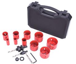
Hole Saw

The sharp teeth of each saw are perfect for making holes in wood, PVC boards, plastic, drywall, and even metal.


They are suitable to drill holes in your RV's roof to pass cables through.

Hole saw set

Cordless Drill

A cordless drill is suitable for drilling pilot holes and mounting screws or bolts on any wall surface. It is just another essential piece of your toolkit.


The cordless drill generally features two-speed transmission sets at low speed (about 500RPM) and high speed (about 1,900RPM), suitable for a wide range of drilling and fastening applications.


The most helpful feature is that this drill does not need an AC plug connection.


Cordless drill

Drill Bits

As a valuable complement to the previous tool, the drill bits are needed for making pilot holes to mount appliances or devices on a wall surface, such as an inverter or a charge controller.


Drill bit set

Safety Goggles

Last but not least, to protect your eyes during the installation of solar equipment, you will need to use safety goggles.


You can generally find them in different sizes to fit the shape of your head, and they can also integrate bi-focal shatterproof polycarbonate lenses. The lenses can be found in various colors, from copper to yellow, gray, smoke, and transparent. These lenses could provide sun protection as well.

Safety goggles


The importance of using safety goggles can’t be stressed enough. Especially when working on connecting your battery and inverter. Always use safety goggles when working on these.


Now that you know the basics of electricity and know which tools you need, let’s continue by listing the equipment you need.

Equipment


Among the topics that you must be aware of installing an effective off-grid solar power system is the basic equipment required. Here you can see a list of items you need when building a solar system.

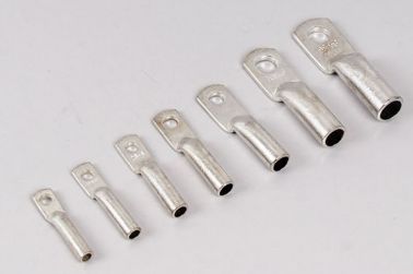
Wire Lugs

Wire lugs are tin-plated copper required to make a solid connection in your system. You will find multiple options available from different manufacturers and materials. You should only use tin-plated copper. Copper is corrosive, and the tin layer will protect it from corroding.


Make sure that the hole fits the battery terminal or inverter connections. You will need a tool to crimp the wire lugs onto the wire, which we discussed in the tools chapter.


Wire lugs for different AWG wire


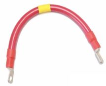
You can buy battery and inverter cables that already have the terminal lugs attached. This way, you don’t need special tools to fit these bigger wire lugs. Remember that the thickness of the wire depends on the current that has to flow through the wire. Buying prefabricated wires if you are using big lugs is recommended.


Adding heat shrink over the lugs will make the connection stronger, which makes the wire ends stiffer. This reduces the chance of breaking the individual wire strands in sharp bends.


Example of an interconnection cable with wire lugs and heat shrink.


Wire lugs are used for big cables only. For smaller wires, crimp connectors are used. Look for UL-listed wire lugs because cheap lugs might not have thick enough material. Your local hardware store will have these.

Crimp Connectors

As we will discuss in the wiring chapter later, you need to use stranded wire. The only downside to using stranded wire is that you need crimp connectors at both ends to connect your terminals to other devices.


The reason for using crimp connectors is that it gives a better point of contact to the device terminals, which reduces heat loss. It will eliminate corrosion at the exposed sides of the stranded wire.


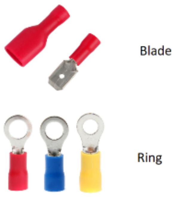
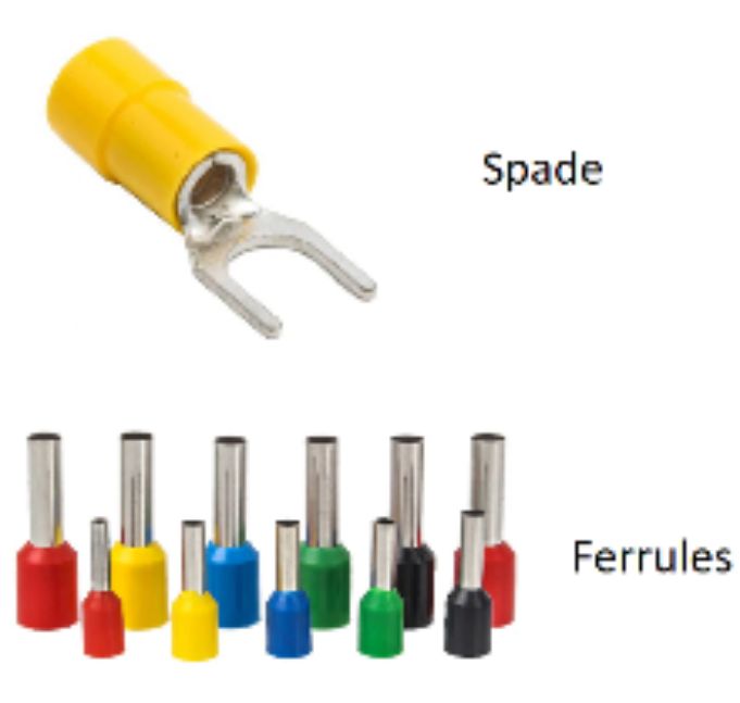
There are several types of crimp connectors:


Several types of crimp connectors


Ferrules, rings, and spades are the most used in solar applications. Ferrules are used to connect to the terminals of the devices, while rings and spades are used to connect to busbars. Bullet connectors are used for MC-4 connectors.


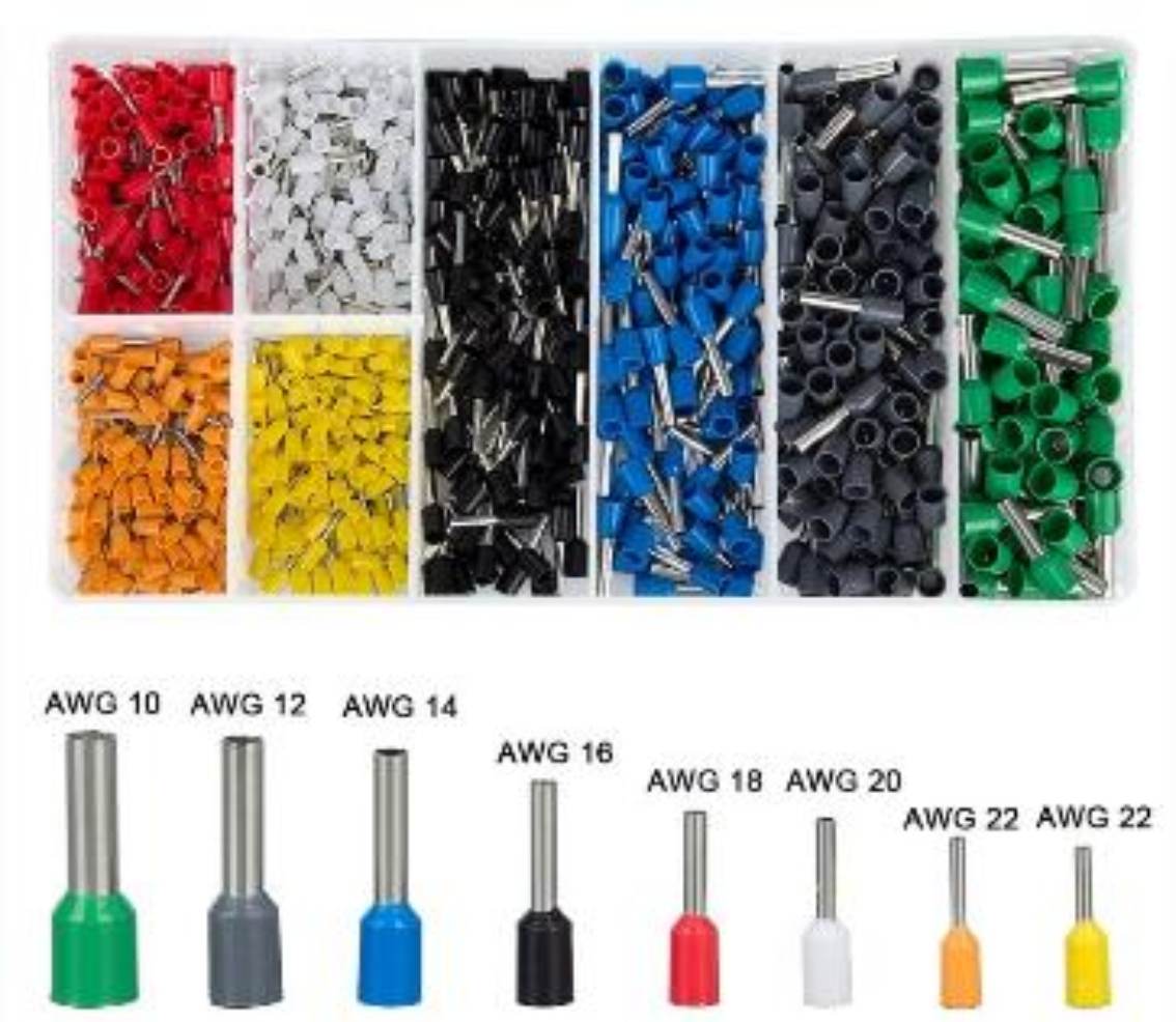
Like most crimp connectors, they come in several colors. Each wire diameter has its color.

Image result for ferrule to wire size

Different sized ferrule connectors


  • AWG 10 (Green)
  • AWG 12 (Gray)
  • AWG 14 (Blue)
  • AWG 16 (Black)
  • AWG 18 (Red)
  • AWG 20 (White)
  • AWG 22 (Orange)
  • AWG 22 (Yellow)

Color coding is not always standardized, so they can differ. Once again, you should buy UL-listed wire lugs.

MC4 connectors

Bullet connectors can be found in MC4 connectors. These are used to bring the electricity from the solar panels to your combiner box or straight to your charge controller. The plastic MC4 connectors protect the cable from moisture, dust, and rain.


They also function as a plug-and-play wiring method for combining solar panels in a string or array (series and parallel).

Several different MC4 combiners


Almost all solar panels come with MC4 connectors these days. Here is a guide on crimping them if your panels don’t come with them.

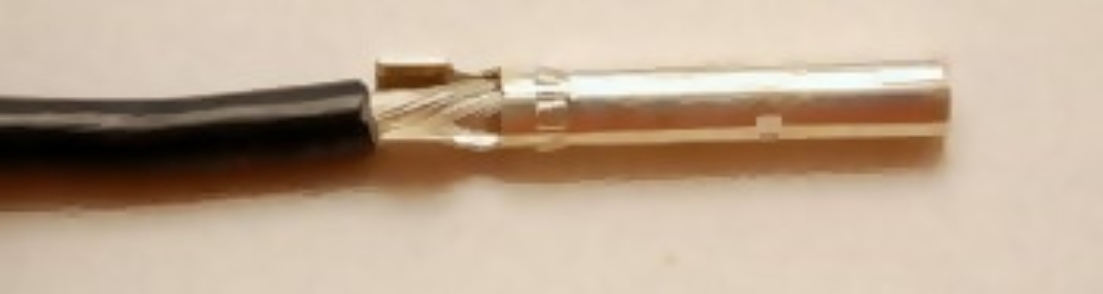
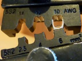
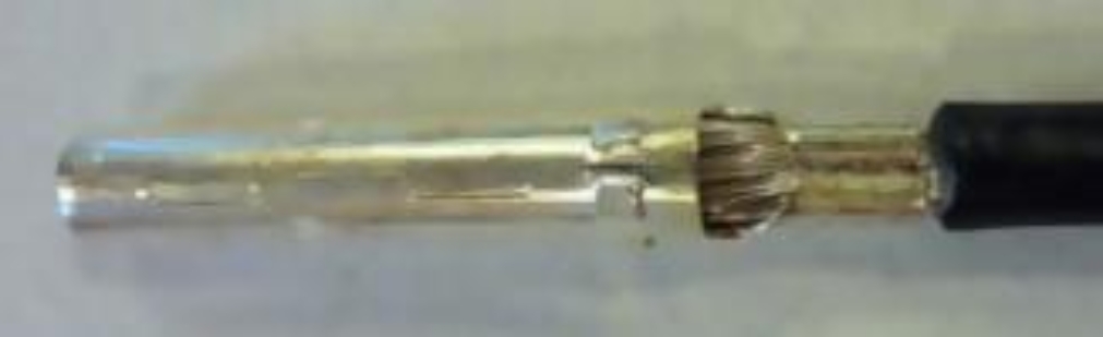
After stripping the wire insulation with a wire stripper, you can place the stripped wire in the bullet connector. Use a crimping tool to apply pressure on the crimp connector to secure good conductivity.


https://marinehowto.com/wp-content/uploads/2017/03/14-Installing-Solar-MC4-Terminals-350x232.jpg

Inserting the stripped wire in the bullet connector


https://marinehowto.com/wp-content/uploads/2017/03/15-Installing-Solar-MC4-Terminals-350x263.jpg

Crimping the wire inside the connector


https://marinehowto.com/wp-content/uploads/2017/03/16-Installing-Solar-MC4-Terminals-350x263.jpg

The crimped wire inside the connector


https://marinehowto.com/wp-content/uploads/2017/03/17-Installing-Solar-MC4-Terminals-263x350.jpg

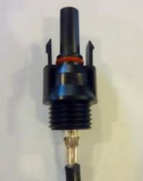
Inserting the crimped connector in the MC4 housing

Source: Marine How-To


Next, you need to tighten the connector to the wire using an assembly tool delivered together with the MC4 connectors.

MC4 Assembly tool


If you do not want to make these cables yourself, you can buy them already made. This is easier and will reduce the possibility of error. Search for ‘MC4 connector cables.’ Make sure you select the correct gauge for the current that flows through it. Parallel connections need bigger wires. More on this later.

Busbar

In electrical power distribution, an element that is crucial to consider in any installation is the busbar. You need to use a busbar when you use three or more connectors or lugs on any terminal (for example, the battery terminal).


These are copper or aluminum strips that can be seen inside switchgear or panel boards that carry the currents in the electrical system. They act as the collection or distribution of electrical currents up to the loads from the source. They are also called central wiring terminals. There are several uses for busbars:


  • Positive busbar
  • Neutral busbar
  • Ground busbar

Small busbars are intended for small, off-grid PV applications with just a few pins for interconnection between components (inverter, charge controller, and batteries).

Small 250A busbar


Check the amp rating of a busbar before you buy it. We will determine the maximum amps in your system in the ‘sizing your solar system’ chapter.

Displays

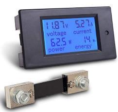
To have a visual indication of the charging state of your battery or how much solar power output is generated, you need to have a display instrument. This device will show the values of the variables related to voltage, current, and power that you can put in an easy-to-access location.


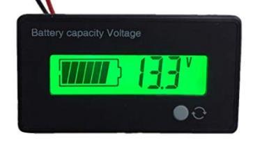
One example of such a case is the battery monitor for a battery bank. In the following image, you can see the voltage level of a lead-acid battery. When the battery is under load (when you are using electricity), the battery's voltage will drop. To get an accurate measurement, disconnect or switch off your loads to get an accurate voltage reading.


Battery voltage indicator


Many other displays are available, an external display from the charge controller or the shunt, which gives you a complete overview of your system. We will talk about these later in the book. Shunts are more accurate and display more information but are expensive. A simple voltage meter is suitable for very small systems.

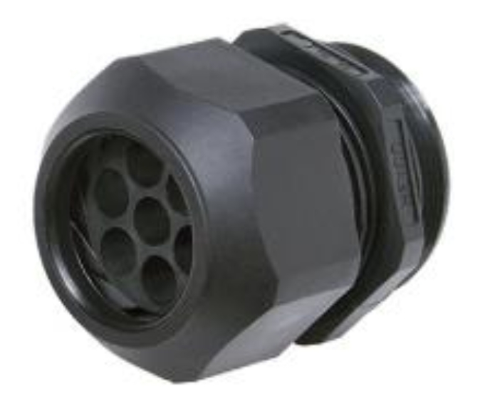
Cable Gland

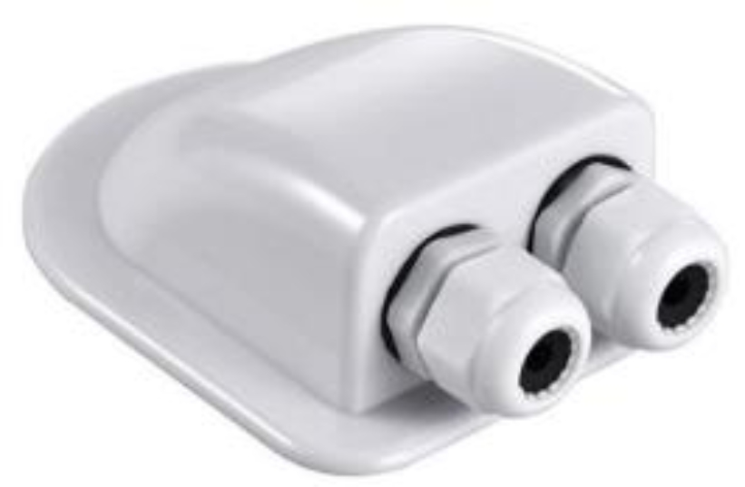
Most likely, you will need to put your cables through the roof of your RV. It’s best to use a cable gland for this. Use roof sealant or lap sealant to make it watertight.


Tip: protect your cables from abrasion against the sharp edges of the hole in the roof. Use protective cable sleeves to stop the wires from cutting themselves and making a short circuit.

Rich solar double cable entry gland


Most people with off-grid solar in RV’s and camper vans will use this kind of cable entry gland.


Depending on the length of the cable, I do not recommend using branch connectors when the combined current is over 20Amps. This is because branch connectors are limited to 10AWG. 10AWG cable can handle 30Amps, but you also have to take into account the voltage drop to the charge controller. More about sizing wire later in the book.


If the combined current of the parallel setup is more than 20Amps, you need a combiner box.

Combiner box

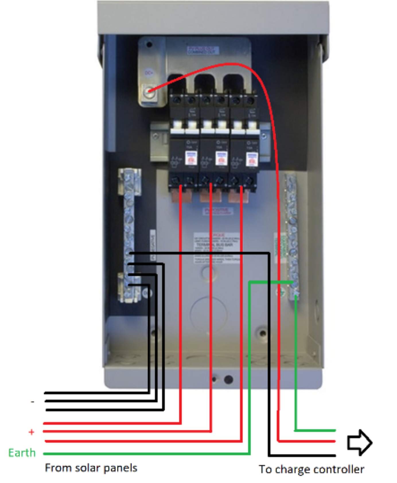
This component is a box that contains all the connections coming from every string of solar panels and joins them in a single wire. It is used when connecting more than a few panels in parallel.


From this connection, three bigger wire gauge output cables (positive, negative, and ground) contain all the generated DC electricity and transport it to the charge controller. The combiner box consists of a negative bus bar, a ground bus bar, a positive bus bar, circuit breakers or fuses, and an optional surge protection device.


The combiner box is usually set as close as possible to the string of PV modules to reduce voltage drop or DC wiring ohmic losses. Therefore, in residential or commercial applications, they are typically placed outdoors, depending on the type of PV system. Refer to the mounting instructions of the combiner box if you are going to use one.


Combiner Box Wiring scheme

Based on MidNite 20A combiner box


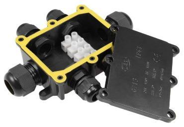
You can use the branch connectors or an outdoor junction box with cable glands for smaller systems like an RV or van.


Small junction box


When selecting a combiner box, you must be aware of several factors:

Encapsulating Rating

Typical encapsulating ratings are classified under the National Electrical Manufacturers Association (NEMA) standards. Typical encapsulating ratings for combiner boxes are type 3R and type 4X.


The type 3R rating enclosure is constructed for either indoor or outdoor use. It protects the equipment inside against incoming solid particles (dirt) and water ingress (rain, sleet, or snow). It also protects the equipment against ice formation on the exterior side.


Meanwhile, the type 4X enclosure-rated combiner box protects all internal equipment from windblown dust and water ingress (rain, sleet, snow, or splashing water). It also protects against corrosion and the formation of ice on the exterior side. Choose IP65 or higher if you want a waterproof box.


Feeding of multiple solar cables should be done using a PV wire cord grip. This plug takes several PV wires and makes the enclosure watertight. You can also use single cable glands.


Image result for pv wire cord grip

PV wire cord grip


The output wire, which goes to your charge controller, needs regular cable glands.

Maximum Voltage Capacity

The combiner box is also designed to withstand a specific voltage rating to provide insulation. Typical low voltage applications for off-grid purposes will be rated at 600VDC.

Fuse or Breaker Capacity

Also, the combiner box will generally have a specific rating for fuses and breakers in volts. The number of breakers/fuses that can be placed inside is important to consider, as this will indicate if the combiner box can connect all the PV strings.


Before we end the equipment chapter, let’s talk about fuses and circuit breakers. It’s a vital aspect of every installation.

Fuses and Circuit Breakers

Fuses or circuit breakers in your solar system are not intended to protect the device it is wired to.


Devices like the charge controller and the inverter have fuses already. We use fuses or circuit breakers to protect the system's wiring from getting hot, melting, or even catching fire.


Therefore, the fuses or circuit breakers are calculated based on the actual wiring. This is to protect your system from catching fire if a higher current flows through the wires for which they are rated. This is how you determine fuse sizes:


  1. Figure out the load.
  2. Figure out the distance to the appliance (voltage drop).
  3. Decide wiring thickness.
  4. Decide fuse rating based on wire thickness.

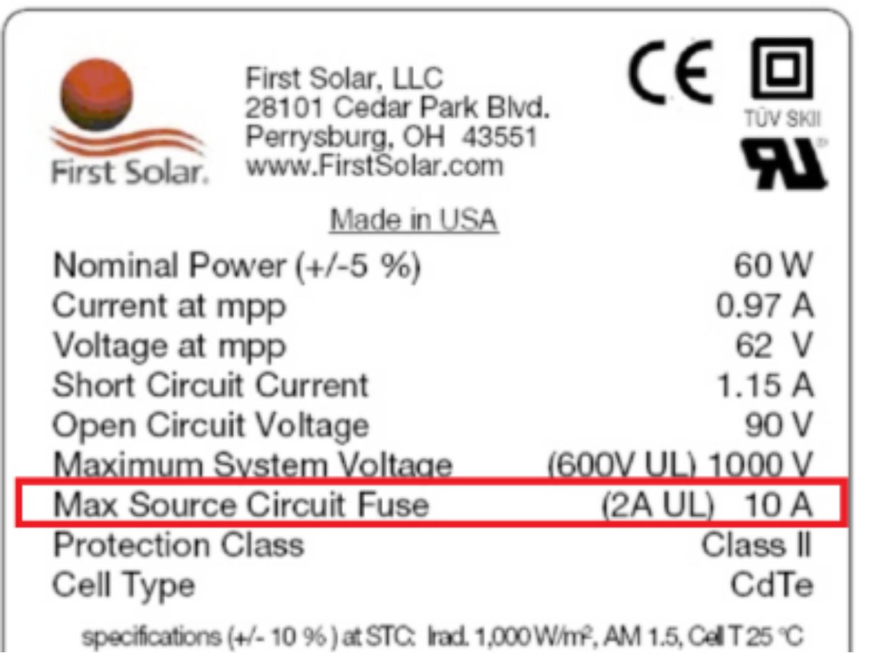
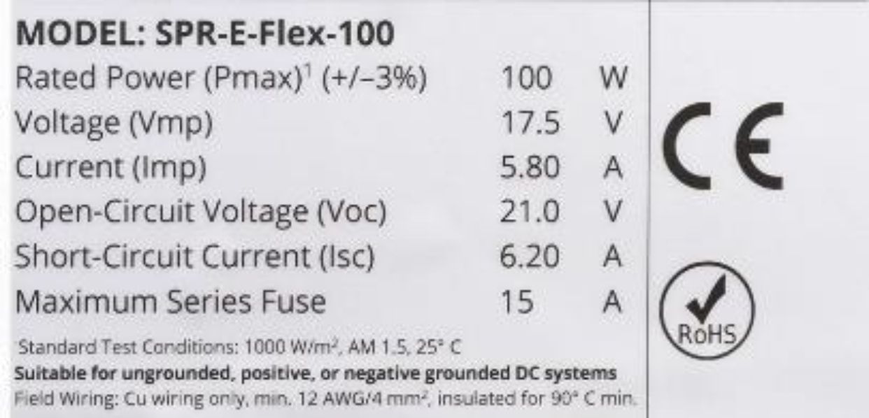
There is an exception to wires that come directly from solar panels. The wiring coming from PV panels is bigger than it needs to minimize the voltage drop. The back of the solar panel will display the maximum allowed fuse size (more on this later).

An example is that you will be running wires rated for 30 Amps to minimize voltage drop, but the maximum fuse for the solar panels is only 10 Amps. We will talk about voltage drop in the wiring chapter.


Technical data of a solar panel

Where to Place Fuses

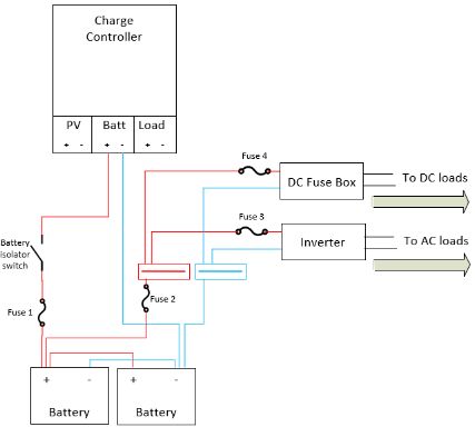
Fuses should be placed as close as possible to the energy source. If current flows from your battery to your inverter put the fuse as close to the battery as possible. If current flows from solar panels to the charge controller, place it close to the solar panels. Only place fuses on the positive (red) wire.

Fuses should be put in the following locations:


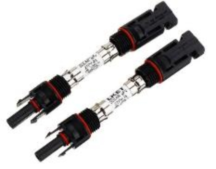
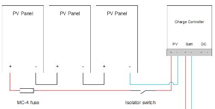
  • On the positive wire from your solar panel(s) to your charge controller. You can use an inline MC4 connector fuse for this. You can put a fuse in a combiner box if you decide to wire in parallel. (More about series and parallel fusing of solar panels later).

Image result for mc4 connector fuses

Inline MC4 connector with fuse


  • On the positive wire from the charge controller to the battery.
  • On the positive wire from the battery to the busbar.
  • One the positive wire from the busbar to the inverter.
  • On the positive wire from the busbar to the DC loads.

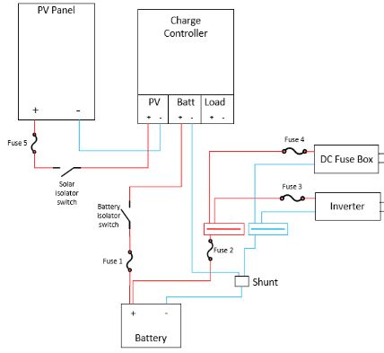
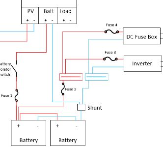
The following circuit drawing will show you where you need to place your fuses.


Placement of fuses in your solar system

Fuses vs. Circuit Breakers

DC protection devices are essential to guarantee any PV system's safe and effective functioning and operation. Always make sure you are using DC fuses in your DC system. When you break DC power, there is a larger arc than AC power. It’s easier to break AC power because it passes through zero 50 or 60 times per second, while DC doesn’t. Therefore, DC protection devices are made differently than AC protection devices.


There are two main types of overcurrent protection devices: Fuses and circuit breakers.

Fuses are devices that contain a filament inside that heats up as current flows through it. When a specific current above the permissible limit passes through the filament, it heats up above its thermal capacity and melts. When the wire inside the fuse melts, the circuit gets opened.


An overcurrent can be created by:


  • An overload caused by excessive current demand from electrical loads.
  • A short circuit caused by a fault that occurs in the circuit.

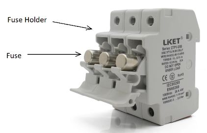
Fuse holder with removable fuses


On the other hand, the circuit breaker is another popular protection device intended for overcurrent protection.


A thermal protection mechanism on a bimetallic contact heats and expands when an electric current above the rated value is present. This protects the circuit against overload. A magnetic protection mechanism instantly responds to high fault currents that protect the electrical circuit against short-circuits or overcurrents.


Two contacts split inside the DC breaker when an overcurrent passes through the protection device, automatically switching it to the OFF position. The DC breaker needs to be put back in the ON position to allow the electric current to flow again. If a fault occurs with a fuse, you need to replace it. With a breaker, you flip the switch back in the on position. Fuses are cheaper than circuit breakers.


DC circuit breakers are expensive; that’s why many people choose DC fuses. Keep a few spare fuses with you all the time.


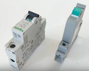
DC breakers


Typically, you would use AC breakers after the inverter in your central AC panel. Use fuses for the DC side because they are cheaper.

Slow or Rapid-acting?

Fuses and circuit breakers are classified according to their response speed.


The acting speed is the time it takes for the fuse to break once a fault current or overload passes through the filament. This depends on the material used for the fuse element and its shape.


Selecting the correct fuse type involves selecting the proper current rating and the response time. Choosing a fuse that acts too fast may not allow normal current operations to run, while selecting a fuse that is too slow may not interrupt faulty currents quickly enough.


There are mainly three fuse speeds:


  • Ultra-rapid
  • Fast-acting
  • Slow-acting

Ultra-rapid fuses are used for semiconductors (electronics) protection.


Fast-acting fuses are used to protect cabling and less sensitive components such as batteries and PV modules.


Finally, slow-acting fuses feature a built-in delay that temporarily allows the flow of inrush electrical currents for electrical motors.


When checking the datasheet of the fuse, you may find some of the following markings, as described in the following table:


Marking

Description

FF

Very Fast Acting Fuse

F

Fast Acting Fuse

M

Medium Acting Fuse

T

Slow Acting Fuse

TT

Very Slow Acting Fuse


Generally, you will need FF, F, or M-type fuse ratings for battery and solar panel protection. You might need to select a slow-acting fuse to allow starting current to flow if you intend to protect a load like a motor or a pump. More on this in the ‘load types chapter’.


Electrical engineers use a detailed analysis of this aspect considering time vs. current graphs of the fuse to ensure that the protection device acts when it needs to.


Let’s look at different fuses and circuit breakers and where you can use them.

Spade Fuses

A type of fuse widely used in solar power applications is the spade fuse, also called blade fuse. These are found in the electrical fuse box of most cars. Their principle is the same as described before. You have to replace them once they trip.


These can be used to act as overcurrent protection for multiple DC loads.


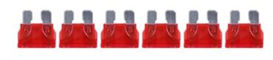
Six spade fuses


The color of the spade fuses indicates their current rating.


Color

Current

Dark blue

0.5 A

Black

1 A

Gray

2 A

Violet

3 A

Pink

4 A

Tan

5 A

Brown

7.5 A

Red

10 A

Blue

15 A

Yellow

20 A

Clear

25 A

Green

30 A

Blue-green

35 A

Orange

40 A

Red

50 A

Blue

60 A

Amber/tan

70 A

Clear

80 A

Violet

100 A

Purple

120 A


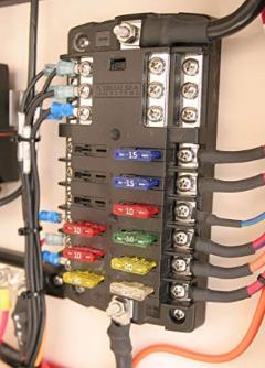
Spade fuses are used in the part of your system with DC loads. Using a fuse box will give you a neatly organized DC load box for led lights or ceiling fans.

Fuse box for spade fuses


Wiring of a DC fuse box using spade fuses

Source: Blue Sea Systems

ANL and bolt-on fuses

ANL fuses are used in off-grid applications, RVs, or boats due to their simplicity and integrated case. These fuses are used for high current applications, mainly on the main battery terminal.


They typically go from 60A up to 500A. Just as with any other fuse, when an overcurrent exceeding the rating of the fuse passes through it, the fuse will break the circuit.


ANL fuses are used for placing in between wires. If you have battery terminals compatible with bolt-on fuses, you should use these. If possible, bolt them right on the battery terminal (as close to the energy source as possible).

Bolt-on fuse and ANL fuse with case

Class-T fuses

Class-T fuses are useful for lithium batteries. Lithium batteries have a low internal resistance which means they can deliver a high amount of current if there is a fault. The batteries can send a high amount of current and bridge the circuit within the fuse, which leaves you with an ANL fuse that cannot stop the current. T-class fuses can prevent this bridging from happening because they are built differently.

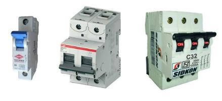
Circuit Breakers

As mentioned before, fuses are better suited for high current DC systems, and circuit breakers are used in AC systems. There are mainly three types of circuit breakers:


  • Single pole
  • Double pole
  • Triple pole

Single-pole models are suitable for most circuitry. Simple loads such as fans, TVs, microwaves, coffee makers, home theater equipment, and any other load that works on 120VAC will need a single-pole breaker.


Other loads such as air conditioners, washing machines, dryers, and some motors work in split-phase configuration requiring 240VAC double pole circuit breakers. Finally, some loads work on three-phase systems at 208VAC. Consequently, they need a triple pole circuit breaker.


Mainly large AC motors will be the ones using this type of breaker. Double or triple pole circuit breakers are not used much in off-grid systems.


A single, double, and triple pole circuit breaker

No-name safety equipment

Buy fuses and breakers from well-known brands only. There is no safe way to test fuses. And when you rely on something for your safety, don’t cut corners. Instead, opt for a brand known for many years in the industry and purchase your equipment from them.


Schneider, ABB, Vynckier, Siemens, and Hager are a few. Check out your local hardware store for reliable safety equipment. They will have good brands available. It can be more expensive, but it will give you peace of mind.

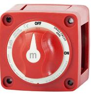
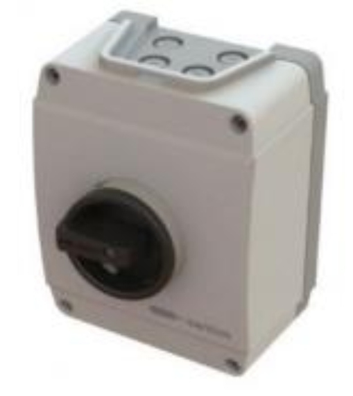
DC Isolator Switch

DC isolator switches are used to decouple parts of the solar system from each other. You will use them during maintenance tasks.


DC isolator switches are put in these locations:


  • Decoupling solar panels from the charge controller.
  • Decoupling batteries from the system.

Before you buy a DC isolator switch, make sure it complies with the system’s current and voltage. For example, the DC isolator switch (solar disconnect switch) from your solar panels to the charge controller has a lower current but higher voltage. In comparison, the isolator switch from the battery requires a higher current but lower voltage (depending on the voltage of your battery bank).


48 Volts DC, 300 Amp battery isolator switch


800 Volts DC, 25 Amp solar disconnect switch


It would be best not to use regular circuit breakers as disconnect switches. This is because they are not built for frequently switching under load. Always buy an isolator switch with a higher voltage and current at a specific point in your system.


Where to place isolator switches

Basic Circuitry

Basic Light Circuit

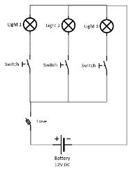
A light circuit is one of the most basic electrical circuits you can have. You will need a battery (power source), a switch (control device), and a lightbulb (load).


Placing the battery with the positive terminal toward the switch and then connecting the bulb between the switch and the battery will allow you to activate or deactivate the light manually.


Basic light circuits


It is a good practice to draw out your system before purchasing the components. You don’t need a professional computer drawing; you can do it with a simple pen and paper.

Short Circuit

A short circuit is described as a non-normal operational behavior of an electrical circuit where a large amount of current flows through an unintended path with low resistance.


Short-circuits are generally associated with two scenarios:


  • Short-circuits between phases.
  • Short-circuits to ground.

A short-circuit happens when a direct contact (metal to metal) between battery terminals or cables with different polarities occurs.

Diagram  Description automatically generated

Short circuit between terminals on a battery


This is unlikely to happen unless you connect the positive and negative from the battery with a single wire (do not try!). Another reason why this can occur is if you drop a tool on the battery terminals. Therefore, you should buy insulated tools described in the ‘tools’ chapter.


The next chapter is about the different load types in an off-grid system. Some of these tips will help you design your system.

Load Types


An important step that you need to do when sizing your PV system is to estimate the load that you will have. This topic covers mainly two aspects: power and energy. An off-grid PV system works as a variable and a limited energy source.


Therefore, you must determine the electrical loads that will consume power in the PV system and specify how long they will be used.


In this matter, it is essential to know the type of loads you will be connecting to the PV system and understand how they work. Let’s see some of the typical loads you will use for off-grid purposes.

Resistive Loads

There are mainly two types of resistive loads:


  • Linear loads
  • Non-linear loads

Linear-type loads consume an average amount of power that is constant over time. There are no significant fluctuations while running or starting them. These are generally associated with the behavior of electrical resistance; therefore, they are called resistive loads. These can be a lightbulb or a water heater.


Non-linear loads have a behavior similar to inductors or capacitors, which have a consumption over time that is not constant. An example of a non-linear resistive load is a computer with a switching power supply. The resistive loads have their power consumption in their datasheets. This power consumption can be expressed in watts or amps.


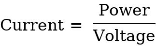
You will typically find the nominal voltage of the load in the datasheet as well. Using the power formula:


, you will be able to find the equivalent power that the load consumes. In the following table, we can look at some resistive loads used for residential purposes.


Appliance

Running Watts

CD/DVD Player

35-100

Clock Radio

10-50

Desktop Computer

60-200

Laptop

20-50

Printer

30-50

Coffee Maker

650-1,200

Hair Dryer

1,000

Blender

1,200

Electric Water Heater

1,500

Fan

30-100

Iron

1,000-1,500

Microwave

1200

24” LED TV

40-50

Air conditioner 5000 BTU

500

Electric Stove

2,000

Electric Blanket

200

LED lights

6-20

Typical resistive load consumptions for an RV


As you can see, the loads that consume more power are the ones that:


  • Heat the space
  • Cool the space
  • Generate heat for cooking

These loads must be selected carefully as they will draw a lot of power and energy from the PV system. Elements such as an electric stove, an electric frypan, or a waffle iron should be avoided and replaced by other energy sources like natural gas. Replacing these energy-demanding appliances will reduce the cost of your system.

Inductive Type Loads

Inductive type loads draw more current during their start cycle. When using inductive loads, you need to consider the surge current when starting these devices.

Refrigerator

The most important of the inductive loads is the refrigerator. The compressor takes a cool refrigerant liquid and transforms it into a hot refrigerant liquid with a higher pressure to complete the refrigeration cycle. The compressor needs an electric motor that generates movement inside the compressor. This means we will have a power surge while starting.


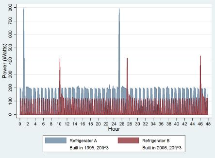
In the following image, you can see the power consumption of two 20 cubic feet refrigerators.

Refrigerator starting pattern old vs. new

Source: Is your refrigerator running?


  • Refrigerator A has a nominal power consumption of 200W and starting power of 800W.
  • Refrigerator B has a nominal power consumption of 100W and starting power of 400W.

As we can see, in both cases, the starting power is four times the nominal power required for operation. Therefore, the off-grid PV system must always provide this surge power.


Another factor you must consider with refrigerators when sizing the PV system is that you cannot take the nominal power consumption and multiply it by 24 hours. This will lead to oversizing and is a common mistake.


Refrigerator datasheets often include a yellow label to find the product's energy consumption per year or day. This is the reference you must use in your calculations for energy yields. Power consumptions must be considered for the inverter’s power rating.


The energy consumption of a fridge depends on many factors:


  • Type of fridge: A top loader will consume less power than a display fridge.
  • Size: The volume of the fridge will play a role in energy consumption.
  • Location: If the fridge is well ventilated at the condenser, it will require less energy.
  • Season: The fridge needs to work harder during the summer because the temperature difference is higher.
  • Usage frequency: Opening the door frequently will lead to more energy usage.
  • Temperature set point: Check to ensure the temperature setpoint is not too cold.
  • Age: The age of the refrigerator also affects energy usage. The newer, the less energy it will use (if it is the same type).
  • Quality of the seals: Cold air will leak if the seals are not sealing well.

Depending on all these factors, refrigerators will generally consume 50% of their rated power in one day. For example, a fridge that is rated at 100 Watts and runs for 24 hours a day will consume:


Many people consider running a DC fridge. While you can buy DC fridges, they are pretty expensive. You might be better of getting an AC fridge and powering it from your inverter. That means your inverter has to stay on all the time. If your inverter is big (let’s say 3kw+), there will be lots of power loss because of idling losses. You can opt for a smaller inverter (500w) that can continually power your fridge but with less power loss. That way, you can shut down your bigger inverter and limit the power loss from idling. Turn on the big inverter when you need it.

Washer/Dryer

There are two types of dryers: gas- and electric-based dryers. Electric dryers circulate an electric current through a resistor to generate heat. Electric dryers consume a considerable amount of electricity that can reach up to 725kWh per year and consume a lot of power, reaching over 3kW.


The amount of energy and power required to supply a dryer is too much for an RV or simple off-grid application with a small space available for solar panels.


The best choice might be to go for a gas-based dryer. Using a dryer that works on natural gas comes with other essential safety regulations like placing it in a well-ventilated place and allowing fresh air to enter the intake of the dryer. This can be accomplished by installing an external intake and exhaust pipe. Installing a propane detector is a good safety precaution.

RV Water Pump

An RV water pump is another type of load that you can add to your list. RV water pumps generally work at 12 VDC. They can draw between 2.5 Amps and 10 Amps under regular operation.

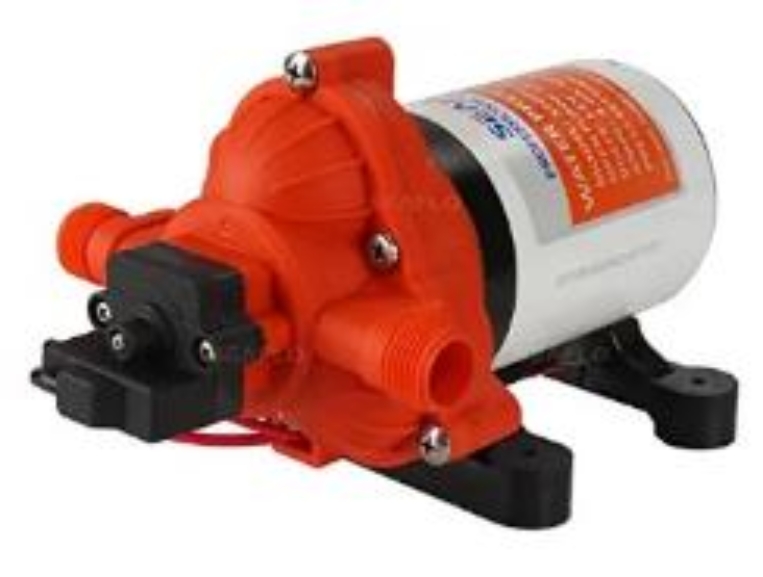
3 gallons per minute RV pump from SeaFlo


However, as they also include a DC motor, they could draw between 10 and 40 Amps during the starting process.


Keep in mind that these 12V water pumps are designed for intermittent use. In other words, they are intended to be used during the time that you take a shower, wash your hands, or the time it takes you to flush a toilet. These are DC appliances that do not count toward your inverter power.

Air Conditioner

The air conditioner is a convenient but very demanding type of load. If you are thinking of powering an AC unit with solar panels, you must accurately estimate the energy consumption that this load will have.


An AC unit’s power consumption cannot simply be calculated based on the nominal power.

Doing this will represent a tremendous increase in energy demand, and your solar panel system will be oversized.


This device also has a motor that runs a compressor. Therefore, it also requires a surge current. For AC units, a reasonable assumption is that the surge power will be equal to three times the electrical power on the technical datasheet.


A common mistake is to assume the air conditioner's energy consumption will be related to the number of hours of use.


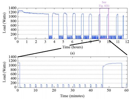
You will notice that energy consumption will be much lower. The following image shows the pattern of consumption of an AC wall unit to give you a reference to performance behavior.


Load curve of an AC unit

Source: Load profiles of selected major household appliances and their demand response opportunities


As you can see, the AC unit will consume its rated power of 1,200 Watts to cool down the room. After that, the compressor (outside unit) will stop while only the fan inside will work. The compressor will have the highest energy consumption.


The energy consumption will greatly depend on the difference in temperature between the inside and outside and time of day, how many times you open the doors, the insulation, just to name a few.


In the next chapter, we will put our knowledge into action. We will show you how to size your system correctly.

Sizing your Solar System


Now that you know the different types of loads and what it takes to run them, we go to work estimating how big your system needs to be to run all your devices.


We will start with a short description of system voltages. After that we get to work on a practical example.


12, 24, and 48V systems

It’s essential to know the consequences of choosing a specific voltage for your system. We will discuss the advantages and disadvantages of these systems for different components.


Charge controller

A single charge controller can handle a maximum of 80 Amps, which equals 960 watts of solar at 12 volts.


Now let’s see what happens when we increase the battery voltage to 24 volts. We now have 1920 watts of solar with the same 80 amp charge controller.


Or even more when we have a 48-volt battery system.


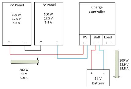
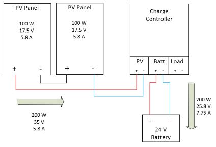
The conclusion here is that your charge controller will be cheaper when you use a higher voltage system. You can have a lower amp charge controller for the same PV input power if you increase your battery voltage. The following image illustrates this.


Diagram  Description automatically generated

Influence of battery voltage on the charge controller


Wiring

Remember the power formula? If the voltage is fixed, we can only increase the current to achieve our desired power output. That means that if the voltage is 12 volts, we have to increase the current to a certain level to meet our power requirements.


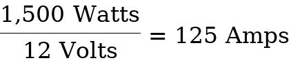
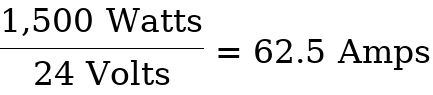
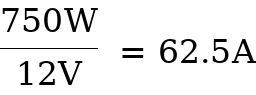
If we have an inverter of 2,000 watts, we can calculate the current going through the wire at 12 Volts, 24 volts, and 48 volts.


Using a 2,000 watt inverter on a 12 Volt system will draw 167 amps. This high current is too dangerous. I recommend staying under 100 Amps in DIY systems, especially if you crimp the wire yourself. Using a 2,000 watt inverter on a 24- or 48-volts system would be much better. Apart from being cheaper, it will be safer and easier to work with because you don’t need big wires.


A fully charged 48-volt battery will be higher than 50 volts at the terminals. Be aware that a 48volt system will be more dangerous than a 12 or 24-volt system.


I recommend using a 24 or 48-volt battery for most systems. The wires will be cheaper, and the cost of the charge controller will be cheaper as well. Be careful with lithium batteries. Some cannot connect more than two in series to make a 48 volt system. This is because the battery management system (MOSFETs) is not compatible with the higher voltage. More on this later in the battery section.


Now that you know the benefits of a higher voltage battery bank let's calculate the rest of the system.

Calculations

Let’s say you are converting a van to an off-grid mobile home. You are planning to use the following devices:


  • Phone charger
  • Laptop charger
  • Water pump
  • 5 DC led lights
  • Speaker system
  • 12V top-loading fridge/freezer combo
  • 12V ceiling fan
  • Blender
  • Egg cooker

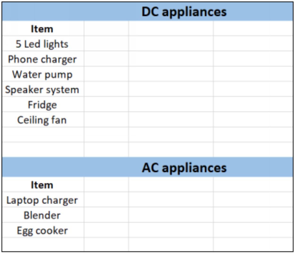
Now, you need to separate the AC devices from the DC devices. Try to do this in a spreadsheet. You can also use my load analysis tool on my website:

https://cleversolarpower.com/load-analysis/


Everything with a standard household plug will be an AC device. Anything that works on 12 or 24 Volts DC goes into the list of DC devices.


Try to use DC devices instead of AC because it will limit the load on the inverter. That way, you can choose an inverter with a lower power rating.


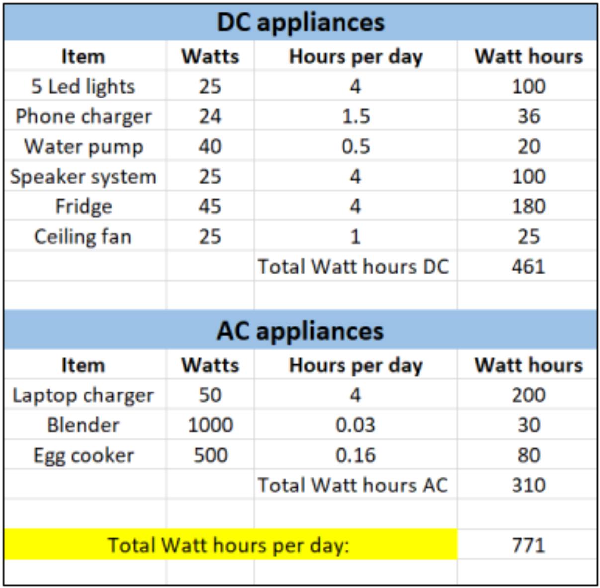
I will enter my devices in the list and separate them by DC and AC.


Categorizing devices into DC and AC


Next, you are going to determine the power rating for each device. There are four options to find the power of a device:


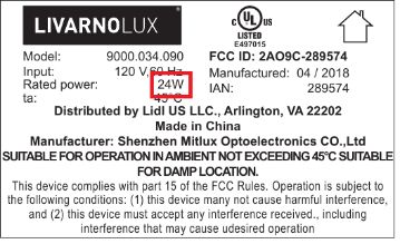
  1. By looking at the sticker.

Start by searching for the sticker on the appliance you want to use. If you are lucky, you might find the power (watts) that the device consumes. If there is no visible sticker on the device, move on to option two.


Sticker on the device


  1. By searching online.

If you have not bought the device yet, or can’t find the sticker, search online. Search for the item name in Google. You will find some websites that list the power rating on their product page.


  1. By using the ‘kill a watt meter.’

If you cannot find the power rating for the device, you can use a ‘kill a watt’ meter to read the appliance's power consumption. This is especially useful for devices that are not constantly in use, like a fridge or an air conditioning unit.

Image result for kill a watt meter

The ‘kill a watt’ meter


  1. By applying the power formula.

The last method is to search for the current of the device. Try to locate the device's current by using method one or two.


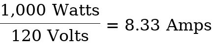
Now, we know the device's voltage, either 12 Volts DC or 120 Volts AC, and we know the current through the device. We can determine the device's power rating.


Let’s take this example and calculate the power it consumes.


This would be different if we were using a DC device. Let’s take a 12V water pump which uses 3,3amps.


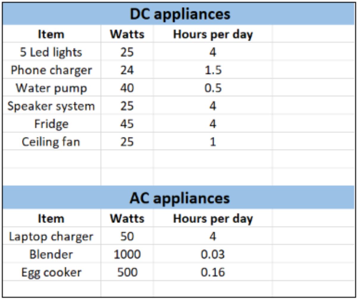
Now we fill in the power of each device in the spreadsheet.


Entering the power rating on the spreadsheet


Now you can decide the power rating of your inverter. If you do not use your blender and egg cooker together, you can use a 1,500-Watt inverter. You should not use a 1,000-watt inverter because the inverter would heat up, which will reduce its efficiency. It will also make more noise because the cooling fan will be running more often.


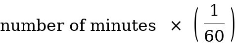
The next step is to determine how long you will use these devices each day in hours. Use the following formula to convert minutes to hours:


I’m using a blender for two minutes each day.


Put the time values in the spreadsheet.


Calculating hours per day


In this step, we will calculate the number of watt-hours the devices consume in one day. We do this by using the following formula, which we have already learned.


For the phone charger, this is:


Calculating the total watt-hours for our system


Now we can add up the total DC and AC Watt-hours.


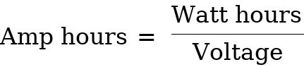
The next step is to calculate the battery we are going to need. Battery capacity is expressed in amp-hours or simply Ah.


Now you need to decide the battery bank voltage. Remember the previous chapter about 12, 24, and 48 volt systems? We are going to limit the current in the wires to a maximum of 100 Amps. Now you can select a voltage level based on your inverter size. It is recommended to use these battery bank voltages for these inverter sizes:


  • Inverter below 1000 Watts: 12V
  • Inverter between 1000 Watts and 2000 Watts: 24V
  • Inverter above 2000 Watts: 48V

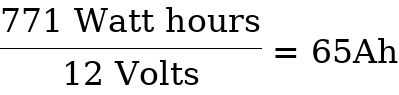
For this example, we will continue using 12 volts for the battery bank. Next, we calculate the amount of Amp-hours the battery needs. 771 Watt-hours is the value we get from our load-analysis table.


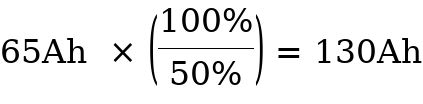
If you use a lead-acid battery, you need to double the capacity because the lead-acid battery can only be discharged to 50%. A 100Ah lead-acid battery only has 50Ah of usable energy. You can get 50% of usable energy out of the lead-acid battery.


Lithium batteries can be discharged to 20%. A 100Ah lithium battery has 80Ah usable energy. You can get 80% of usable energy out of the lithium battery. While you technically can get 100% usable capacity, using only 80% will give you a longer lifespan.


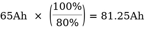
A requirement of 65Ah per day will need a battery with the capacity of:


For lead-acid:


For lithium:


Unfortunately, there will be some days of shade where your batteries will not be fully charged. This will depend on:

  • The place you have your setup (latitude).
  • Time of year (summer or winter).
  • Weather (cloudy or sunny).

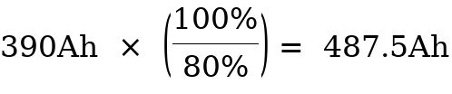
It is recommended to have at least two days of autonomy, but three days is better. This means that you need a battery bank that is:


For lead-acid:


For lithium:


Next, you need to consider the efficiency of the type of battery you will use. Here are the efficiencies of various batteries:


  • Lead-acid: 80%
  • AGM: 90%
  • Lithium: 99%

For lead-acid:


For Lithium:


If you are using a lead-acid battery, you need a battery of 487.5Ah at 12 Volts.


If you are using a lithium battery, you need a battery pack of 246.2Ah at 12 Volts.


The next step is to determine the recommended power of the solar panels to charge the battery in one day. To do this, we need to convert our battery bank size from amp-hours to watt-hours. We have chosen a 12 Volt battery system, so we will multiply the amp-hours by 12 Volts.


For lead-acid:


For lithium:


Remember that you can use 50% of the energy and a lithium battery 80%? That means there will be 50% for lead-acid and 20% for lithium left in the battery at all times. Let’s calculate the usable watt-hours that can be stored in these batteries.


For lead-acid:


For lithium:


The amount of watt-hours we have calculated is needed to supply the system within one day to recharge the batteries fully.

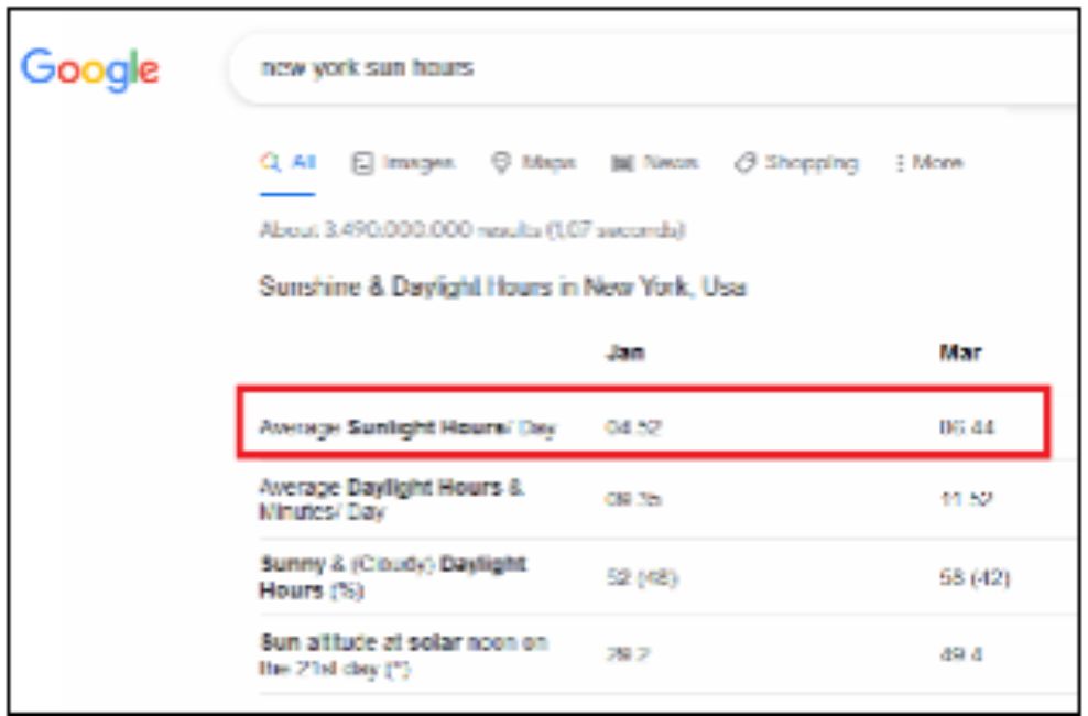
The number of sun hours that hit the surface ranges from 4 to 8 in the united states. For New York, this is 5 hours. The number of sun hours for your location can be found with a quick google search.


Sun hours in New York


We need to use the worst-case scenario (winter), and we will use 5 hours of available sunlight in a day. Then we divide our required watt-hours by the hours of sunlight per day.


For lead-acid:


For lithium:


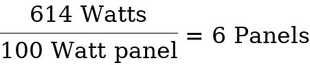
When you buy solar panels rated at 100 Watts, they will deliver this power in standard test conditions (more on this later). This means that the panel will not provide 100 Watts. We need a safety margin of 30%. Therefore, multiply the required power by 1.3 to get our usable power.


For lead-acid:


For Lithium:


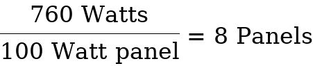
Choose which solar panel you are going to use. In this example, we will be using 100-Watt panels.


For lead-acid:


You need eight panels of 100 Watts each to charge your 12V lead-acid battery bank in one day.


For lithium:


You need six panels of 100 Watts each to charge your 12V lithium battery bank in one day.


Now that we have calculated your system, we will look at connecting it all together.

Wiring

Wiring is an essential part of any electrical installation. Solar installations also need special considerations in this matter.


In this chapter, we will look at the wire core material, different types of wires, factors that contribute to wire sizing, and how to calculate the diameter of the wire.

Wire core material

There are many types of wiring you can use. It is recommended to use stranded wire, which consists of multiple wires in one. This has the advantage of being flexible, while solid cables are tough to work with. Furthermore, stranded wires are better for DC applications than solid-core wires.

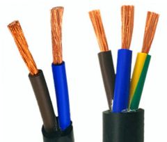
Stranded flexible wires


If you buy wires in the store, you will have three options:


  • Copper wire
  • Copper-clad aluminum
  • Aluminum wire

Copper wire is a better conductor than aluminum, but it is also more expensive.  Since copper is a better conductor of electricity than aluminum, you need to increase the diameter of your aluminum wires to account for this—more information about this later.


Most of the wires sold online are copper-clad aluminum. It means that while you think you are buying copper cables, you get aluminum cables that look like copper cables. People who are unaware of this purchase the copper-clad aluminum and size their wires based on copper cable. This can be very dangerous! Always use copper wire, and don’t save money on your wires.

Sizing Factors

Wires are rated according to the wire diameter. We will use the American Wire Gauge (AWG) throughout this book. Each wire type will offer a different current capacity (ampacity) rating depending on the selected size.


These are classified in pair numbers that go from #18AWG up to MCM scale cable sizes (which will not be used here). We will only use cables between #12AWG up to 2/0AWG wire sizes for our solar PV off-grid applications.


To size the wire that you need for your PV system, you must consider these factors:


  • Current Capacity or Ampacity
  • Ambient temperature
  • DC voltage drop

Let’s take a closer look at what these terms mean.

Current Capacity

The wire manufacturer provides the current or amperage capacity in their datasheet.


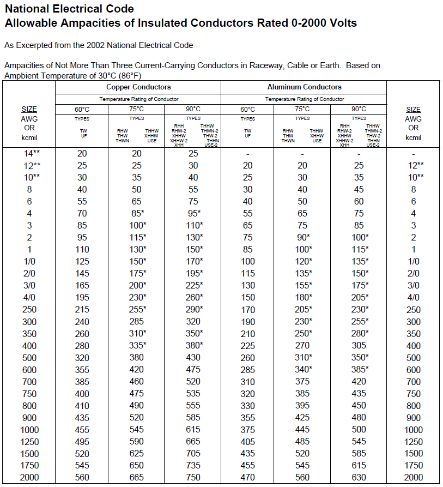
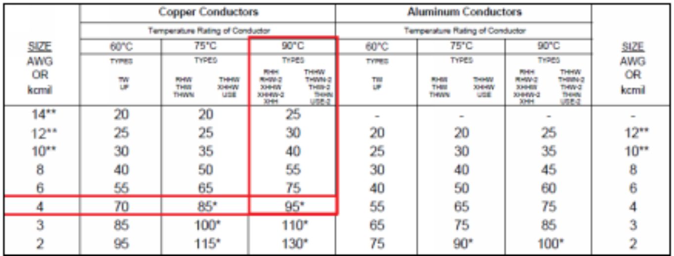
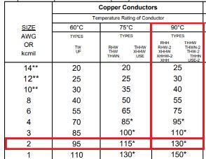
The following table offers a reference from the National Electric Code. In the left column, you see the sizes of the wire, ranging from 14 to 2000. 14 is the smallest diameter while 2000 is the biggest.


On the top, you see the wire core material. This can either be copper or aluminum. It is recommended to use copper.


Below that, it shows the temperature rating of the insulation. This can be 60°C (140°F), 75°C (167°F), or 90°C (194°F). Choosing a wire with a higher temperature rating is always better. Under the temperature ratings, you can see the different types of wire. We will talk about these in the next chapter.


Then the last and the most prominent data representation we can see on the table is the ampacity rating of the conductor or the amount of current that can go through the wire.


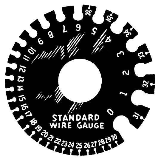
American wire gauge - Wikipedia

A selection of the American AWG wire sizes (not on a real scale)


Ampacity ratings for multiple insulated conductors.

Source: National Electric Code


To view a PDF of this chart, go to:

https://cleversolarpower.com/ampacity-ratings

(direct download)


To select the correct wire size, you must estimate the maximum electrical current that will flow through that wire section and then select the wire gauge that withstands that amount of current.


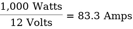
For example, A 1,000 Watt inverter that feeds itself from a 12 Volt battery has a current of:


If we use THWN-2 copper wire with insulation rated at 194°F (90°C), at an ambient temperature of 83°F (30°C) and use the previous table, we need a 4AWG wire.


Selecting wire diameter

Temperature Correction

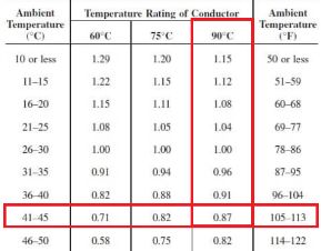
There is another factor that needs consideration, the ambient temperature. Ambient temperature also influences the resulting temperature of the conductor, and it can increase it (hot climate) or decrease it (cold climate).


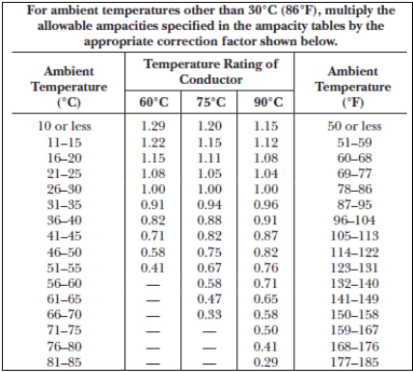
The electric current values of the previous table are calculated assuming an 86°F (30°C) ambient temperature.  This may not be the temperature in your location or even the temperature inside the battery compartment. Therefore, a temperature correction factor must be applied. We can account for this using two methods: equation or predetermined tables.


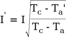
The equation method consists of applying the following formula:


Where:


I’= Ampacity corrected for ambient temperature.

I= Ampacity shown in the previous table.

Tc= Temperature rating of the conductor (°C).

Ta’= New ambient temperature (°C).

Ta= Ambient temperature used in the table (°C).


The I’ value will represent the new ampere rating permissible for that conductor in that specific ambient temperature.


The formula looks very intimidating, but it is easy to explain with an example.


Let us assume you need a copper THWN-2 #2AWG cable. At 194°F (90°C), it has an ampacity of 130A.


Let’s assume that the ambient temperature inside the battery compartment is 104°F (40°C). The expression would be as follows. The 30°C is from the standard NEC table.


This means that the new current carrying capacity of the wire will be reduced from 130A to 118A. As you can see, the ambient temperature can have a significant impact.

The second method uses pre-established correction factors by temperature ranges using the values found in the following table. This method can be easier.


Ambient temperature correction factors for ampacity.

Source: National Electric Code


Visit this link for a better visual of this table:

https://cleversolarpower.com/temperature-correction


In this case, let’s assume that the ambient temperature reduces to 59°F (15°C) and that your current demand estimation value is 140A, which makes you select a THWN 1/0 AWG cable rated for 75°C.

Selecting a 1/0AWG cable


Now, since the manufacturer has rated the cable at 167°F (75°C) and ambient temperature is 59°F (15°C), then the temperature correction factor would be 1.15.


The next step is to apply the following expression:


We can see that this wire will be able to carry more current than it is rated for. This is because the colder it is, the more efficient the wire will work. We could use a 1AWG wire to carry 140 Amps of current in this situation.


However, when calculating this, you should always use the worst-case scenario. This means using the warmest value your wire will be susceptible to. Let’s re-do this calculation with realistic numbers.


Let’s say the hottest time of summer is about 105-113°F (41-45°C). From the table, we can see the corresponding temperature correction factor.


Correlating temperature factor


We now see that this wire can only carry 123 Amps instead of 140 Amps at the specified temperature safely. We need to increase our wire sizes to account for this.


If we are using a 2/0 AWG wire rated for 175 Amps, we become the required 140 Amps in the worst-case scenario. This concludes that you must use a 2/0 AWG wire rated at 75°C.

DC Voltage Drop

When selecting wire gauge sizes, the other factor that must be considered is the voltage drop across the wire. The voltage drop is referred to as losses in the cable. If your cable diameter is small and long, the voltage drop will increase.


For example, a single solar panel with an 18 Volt output, wired to the charge controller with a 5% voltage drop, will lose 0.9 Volts.


The initial 18 Volts drops to 17.1 Volts, which is not ideal. To remedy this, we need to reduce the resistance in the wire by selecting a wire with a bigger diameter.


Voltage drops are associated with the wire size selected, the length of the cable, and the voltage of the system. Voltage drops are undesirable in a PV system because they lead to power losses. They also influence the minimum voltage input rating for various devices.


Therefore, you must calculate the voltage drop for a specific wire gauge and verify if that voltage drop is permissible or not.


Common standards for this parameter establish that a voltage drop lower than 3% must be ensured between the modules and the charge controller. A lower voltage drop of 1% is preferred.


To calculate the voltage drop, you must apply the following expression:


Where:


A= Transversal section of the cable [

ρ= Specific Resistance [Ω

for copper

for aluminum

2= Total travel length for both + and - wire

l= Length of the cable [m]

I= Nominal current through the cable [A] (Imp in this case)

= Permissible voltage drop in the cable [no unit] (1% is 0.01)

Vsys= Open circuit voltage [V] (Vmpp of the string)


For example, we can consider two solar panels in series with 82ft (25-meter) cable length to the charge controller. The string has a maximum power point current (Impp) of 5.8A and a maximum power point voltage (Vmpp) of 35V ().


The desired voltage drop in the system will be 1%.

Applying the expression:


As you can see, the result is given in mm2. This represents the transversal section that the copper wire must have to limit voltage drop to 1%. We can calculate the mm2 to AWG by referring to the following table. As listed in the following table, we would require a #4AWG size cable for this application.


AWG to mm2 conversion table

Source: GEMSA


Voltage drop is significant when the length of the wire is long. This is from the solar panels to the charge controller. It doesn’t need to be calculated for the rest of the system, as long as the components are close together.


Next, let’s look at the wire types.

Wire Types

We can divide the type of wire that you need to use by sections of the PV system:


  • Solar panels - Combiner box
  • Combiner box - Charge controller - Loads
  • Battery cables

Solar Panels – Combiner box

According to the UL-4703 standard, there are mainly two types of wires for PV applications that must be considered for the connection of PV modules.


The best type of wire that should be selected for standard RV, boat, or roof applications is called the PV wire. The PV wire is a single-conductor wire that connects the solar panels in series or parallel to the combiner box or directly to the charge controller.


These wires meet UL-4703 requirements, and they are made of either copper, aluminum, or copper-clad aluminum.


Image result for UL-4703 connector

UL-4703 PV wire with MC4 connectors


Their insulation cover is based on cross-linked polyethylene (XLPE) or ethylene-propylene rubber (EPR), and they are rated to work at 600V, 1kV, or even 2kV.


The most important factor that makes these wires different from others is that they are designed to endure intense ultraviolet (UV) radiation to which the wires will be exposed.


Other wires would deteriorate over time and get their insulation damaged, which could cause exposure of the copper or aluminum material and lead to short-circuit failures. The temperature rating of these wires is close to 195°F (90°C) under wet conditions and between 220-300°F (105°C-150°C) under dry conditions. Also, a PV wire is designed to be flame-retardant, which is an essential feature for the safety of your system.


These wires must be used to connect the solar panels up to the combiner box. They can also be used for connections directly to the charge controller if you do not have a combiner box.


The second type of wire that can be used is the USE-2, which stands for underground service entrance wire.


The USE-2 wire is also used in solar PV applications, especially in ground-mounted applications. The wires can go underground and are considered the alternative option when the PV wire (UL-4703) cannot be purchased. This type of wire is rated at 600V (suitable for solar purposes). They are cheaper than PV wires. However, they do not have UV protection. They are not flame-retardant, and their maximum operating temperature under dry conditions is 195°F (90°C). USE-2 is also less flexible than PV wire.


It is recommended to use PV wire (UL-4703) because it’s more temperature resistant, flexible, and has thicker insulation. It is not forbidden to use the regular USE-2 wire.

Combiner box – Charge Controller – Loads

In this section, there will be no exposure to sunlight. Therefore, wire insulation can be simpler. You should use marine-grade wires for mobile and boat applications. These have smaller strands which makes them more flexible. The small strands will not break with vibrations.


Marine Grade Tinned Battery Cable 2 AWG ( Size 2 Gauge ) Red - Copper  Flexible Stranded

Flexible marine grade wire


You can use copper wires with a tin coating. This will make them more corrosion-resistant.


For cabins or tiny homes, you can use a THW wire. These are flame-retardant, moisture, and heat resistant in a thermoplastic insulation. These wires are rated at 75°C.


These wires are used for machine tools and the internal wiring of multiple appliances. They are rated to work at 600V, up to 195°F (90°C) in dry conditions, and 140°F (60°C) under wet conditions.


THW wire


These wires are less flexible than marine-grade because they have less, but thicker wire strands. If you want to use very flexible wire, use marine-grade wire.


You can use these wires indoors. Do not use these wires outdoors or near your battery. There are other wires which are suitable for the batteries.

Battery Cables

The batteries will generally be located in a separate compartment, depending on your off-grid application. During summer, these spaces could be exposed to high temperatures and an increase in humidity. Deep cycle batteries that are used for off-grid purposes would occasionally expel internal gases to the environment. However, they would expose chemicals to the wires in case of damage or leakage.


Therefore, a THW will not be suitable for this section. In this case, you must use a THWN-2 cable.


THWN-2 wire


THWN-2 stands for Thermoplastic Heat and Water-Resistant Nylon Coated. This cable is suitable for temperature ratings of up to 195°F (90°C) in dry and wet locations. They also have a flame retardant feature, and they have a high resistance to abrasion from oil and chemical agents, thanks to the nylon coating.


These features make it ideal for applications where you need to connect batteries. Alternative options that can be considered are:


  • THHN (Thermoplastic High-Heat Resistant Nylon Coated)
  • XHHW-2 (Cross-Linked Polyethylene High-Heat and Water Resistance)

These wire types must be used in the battery compartment between the charge controller and the battery system and interconnections between batteries if you do series or parallel connections.


This means that the wire from the charge controller should be of this type. The wire that goes to the busbar, inverter, and DC fuse box should also be this type of wire because they all start or end in the battery compartment.


As we have previously talked about, these wires use fewer strands because the individual wires are thicker. Use marine-grade wires if you want very flexible wire or have an RV or boat.


Calculating Wire Sizes

In this chapter, we will calculate the wire size you need for each section of your solar system.

PV Modules – Combiner box

In this section, your reference must be the short-circuit current that is established in the datasheet of the PV module and then apply a security factor associated with higher irradiance levels, as well as the voltage drop. The maximum current a solar cell can produce is:


Sunpower 100-Watt PV module specifications


Calculate the maximum current through the wire:


For this section of the PV system, you will note that wire sizes with a manufacturer’s temperature rating of 90°C can be as small as #14AWG.


However, this is without considering voltage drop. Therefore, we need to calculate the wire size to reduce the voltage drop to an acceptable 1% at 20ft (6 meters). This formula can be found in the chapter ‘sizing factors – voltage drop’.


11.37mm² or #6AWG is needed to wire the solar panel to the combiner box. However, if you buy MC-4 connector cables, they will only be available in #10AWG. They limit the voltage drop to 3% instead of 1%. Let’s calculate it again with a 3% voltage drop.


3.79mm² is a #10AWG wire. This will only be the case if you wire the cable for 20ft (6meters) without an extension. Therefore, you must calculate this correctly to avoid unnecessary power loss. A voltage drop of 3% is acceptable but not ideal. Get your voltage drop as low as possible while your wire is still affordable.


This wire will be used for every connection between modules and send the electric current up to the fuses in the combiner box or straight to the charge controller.

Combiner box – Charge Controller

The output of the combiner box will go to the charge controller. This section will contain all the electric current that flows from the solar panels. If you wire your panels in series, you do not need to use this formula. Instead, to estimate the wire size, we must use the following formula:


The number of strings represents the number of parallel connections made in the solar array, and the factor 1.5625 is associated with security factors.


For example, one array of two panels in parallel:


Calculate the voltage drop if the wires travel 16ft (5 meters) from the combiner box to the charge controller:


Using a 1% voltage drop:


Using a 3% voltage drop:


If you have your panels connected in series, the voltage will increase, but the amperage will stay the same. That is why a series connection is preferred to limit the voltage drop.


Example of the same two panels in series with a 1% voltage drop:


We can see that a series connection requires a wire with a smaller diameter. This is because the wire diameter is decided by the number of amps that run through the wire. In parallel, amps will be added up while voltage stays the same. In series, the voltage will be added up while the current remains the same. More on this later in the book.

Charge Controller – Battery

The current that flows from your charge controller to the batteries will have a maximum charging current listed in its datasheet.


It will also recommend the wire size. There is no need to calculate this wire for voltage drop if the cable is not long.


Following the manufacturer’s recommended guideline is the best advice to follow. If you do calculate this yourself, make sure the terminals of the charge controller are big enough to accept your wire diameter.


Charge controller recommended battery and load cables

Source: Epever

Battery – Inverter

To size the wires that go from your batteries to the inverter, you need to know the power rating of the inverter you will use. For example, if you are using a 1,500 Watt inverter with a 12 Volt battery bank, you apply the following formula:


You need a wire that can supply 125 Amps to your inverter.

Next, you need to choose the temperature rating of the wire. Because we are using a different type of wire (THWN-2), the temperature rating of the conductor will be at 194°F (90°C).


Selection of 2AWG wire


Next, decide the maximum ambient temperature in the battery compartment. In this example, the maximum temperature in the battery compartment up to the inverter will be 105-113°F (41-45°C).


Temperature correction factor


Applying the temperature correction formula:


We can see that we do not get to the 125 Amps our inverter can draw by using the temperature correction factor. Therefore, we need to increase the wire size. Instead of #2, we use #1AWG, which can safely carry 150Amps. Now we apply the same formula with the #1AWG wire:


If we select a #1AWG wire, we can handle the maximum current the inverter can draw. The voltage drop is not calculated because the distance between these two should be almost negligible (few feet).


One advantage of using a system with a higher voltage is that you don’t need to use big wires. If you have the same inverter with a battery bank of 24Volts, you only need a wire that is capable of transporting 62.5 Amps, as can be seen in the following calculation:


It is not recommended to use a wire which carries more than 100 Amps in a DIY system. If your wire carries more than 100 Amps, use a system with a higher voltage. This will not only increase safety but saves you on wire costs too.

Interconnecting Batteries

In this section, the reference will be the maximum charging or discharging current that will flow through the batteries. The discharging current will most likely be the highest.


If you are interconnecting batteries, they should have the same diameter and length. For more information about this, refer to the ‘batteries’ chapter.


The thickness of the wire depends on the total current draw of the loads in your system. If the total load current in your system is 100 Amps at 12 Volts, then size your cables on that number.

Wiring for Electrical Loads

This section applies to DC and AC loads.


Typical DC loads will work with #14AWG or even #16AWG wire sizes.


Typical AC loads such as lighting, TVs, microwaves, fans, small motors, and others will generally use #12AWG or #10AWG wire sizes. These are typically used for outlets.


A/C units, washing machines, and refrigerators may require #8AWG and up to #6AWG, depending on the model.


You can find the electric current demand for your appliance on the product or in the product's datasheet. If you are only presented with the power rating, use the following formula to figure out the current:


For an AC appliance:


For a DC appliance:


Wire Safety

Having a lot of wires close to each other will be inevitable in compact off-grid solar installations. Therefore, there are some rules you need to follow, especially if your system has vibrations like an RV or a boat.


  1. Always protect your wires with a wire sleeve when the wire passes a bend or another wire. This is to protect the insulation from being cut, which can make a short.
  2. Do not make sharp bends with wires. This can damage the wire strands and the insulation over time.
  3. If possible, run your wires through a conduit. It’s easier to add more wires later on.

Protective Sleeving Selection Guide | Engineering360Amazon.com: Allstar Performance ALL76612 Braided Wire Wrap: Automotive

PVC and braided wire sleeve


Batteries

How do Batteries Work?

Batteries work through an electrochemical process that involves a double conversion of energy. The first conversion is to charge the battery and change from electrical to chemical energy. The second conversion process is developed from chemical energy to electrical energy. This is done during the discharge process.


All batteries base their functioning on this principle. To make this energy conversion possible, two electrodes from different metal components must be used to act as the positive and negative terminals of a voltage source. Also, there must be an ionic medium that connects both electrodes. This is commonly known as the electrolyte and is a liquid composition that allows the transfer of electrons between electrodes. This whole arrangement receives the name of the voltaic cell. The collection of several cells makes the battery.


A direct current voltage source must be connected with the correct polarity to the terminals (electrodes) of the battery to get it completely charged. To make electric current flow from the source to the battery, the voltage of the DC source must be higher than the battery.


Lead-Acid

As stated before, lead-acid batteries have two electrodes. One electrode acts as the positive terminal and is filled with lead oxide (PbO2), and the other acts as the negative terminal and is made of pure lead. That’s why lead-acid batteries are heavy.


The medium used for lead-acid batteries is sulfuric acid. Lead-acid batteries can be classified into two main groups:


  • Flooded (VLA or valve lead-acid)
  • Sealed (VRLA or valve-regulated lead-acid)

Let’s look at them in more detail.

Flooded

The first type of lead-acid battery is the flooded or valve lead-acid battery (VLA). VLA batteries are identified by having a small ventilated access to their internal structure with removable plugs that allows verifying of the specific gravity and the state of charge of the battery.


The main downside of these batteries is that they emit gases that are generated by internal electrochemical reactions. Due to this fact, these batteries must be located in an area with vented access where air circulates constantly. The accumulation of these gases within a small, closed area can be dangerous.


Image result for flooded lead acid battery

Flooded deep cycle lead-acid battery


The internal electrochemical reactions and the expulsion of gases also reduce water levels inside the battery. This is why they require periodic maintenance by adding distilled water to the battery through the caps on top.


Maintenance also involves cleaning the terminals to remove oxide that can accumulate over time. You can recognize flooded batteries if you see removable caps on top. The caps can be removed easily with a twisting mechanism. Do not confuse it with the sealed lead-acid batteries, where the caps are not meant to be removed.


Keep in mind that VLA batteries must always be placed in the upright vertical position. Otherwise, the internal fluid will spill out. At the same time, vented batteries can also be classified into three categories.

         Ignition Batteries

These batteries are used for automotive purposes. They seem to be economical for solar builds, but they are not.

Ignition batteries are made to deliver a high amount of current for a short time. This makes the construction of the battery different and not suited for long-duration low current applications. They are also called SLI batteries.

         Deep Cycle Batteries

Deep cycle batteries are used for applications where low amounts of current are needed, but for longer. These batteries can endure many charge and discharge cycles. Since these are requirements used in photovoltaic applications, this kind of lead-acid battery is used for solar power storage.

         Backup Batteries

These batteries are used to provide energy in control operations and backup in sub-stations. These are generally not used for off-grid solar power applications.


You might be able to pick these up when a power company, factory, or hospital wants to switch their backup battery bank every few years. However, these are not considered as the first choice for lead-acid batteries in solar systems.

Sealed (VRLA)

Sealed in the second type of lead-acid batteries. These are partially sealed to avoid the evaporation of electrolyte. VRLA stands for valve-regulated lead-acid. They have a pressure-sensitive valve that automatically controls the emission of gases, but in normal operation conditions, they are closed. They are opened automatically to release gases in case there is high pressure inside the battery. This will happen if there is something wrong with the battery, like a short circuit.


Related image

Valve regulated lead-acid battery

Source: thewolfweb.com


These batteries recombine oxygen and hydrogen through an electrochemical process that allows them to reincorporate water back into the cell instead of evaporating it and constantly releasing it as the VLA batteries do.


Thanks to the pressure valve, gas emissions and contaminations are minimum. The downside of these batteries is that, in some cases, there is a higher sensitivity to the operating temperature when compared to flooded batteries.


There are two other types of VRLA batteries, depending on the electrolyte: Gel and AGM.

         Gel Cell

These batteries have a silicon compound. When added to the liquid electrolyte, the substance acquires a gel-type consistency.

Gel cell batteries have a longer lifespan when compared to flooded-type batteries and guarantee more charging and discharging cycles. This gel consistency is also a significant advantage. Even when the battery is not placed in the upright position, or if the battery case breaks or deteriorates, the sulfuric acid will not spill because the gel structure is solid.


Gel-type batteries also withstand deep cycle discharges with high-temperature values and even vibrations. Besides, they have a stable voltage during the discharge and do not require maintenance as vented batteries do.


They are also corrosion-resistant and are resistant to lower temperatures. However, their main disadvantage is high internal resistance, which translates into a lower discharge current (C-rate). Gel batteries have a life cycle of around 1,000 cycles when discharged to 50%.

         Absorbed Glass Mat (AGM)

In AGM-sealed batteries, the electrolyte is absorbed by fiberglass that works as a sponge that immobilizes the sulfuric acid. AGM batteries offer the same benefits as gel cell batteries. The difference lies in that AGM batteries withstand higher charging voltages than gel types but are not immune to high voltages. They will still offgas.


These batteries have a lower internal resistance due to their structure, which is why AGM batteries can deliver or absorb higher electrical currents during charging and discharging when compared to gel-type batteries. A lower internal resistance also increases efficiency.


Unlike VLA batteries, these models can be placed vertically or horizontally. The charging current represents 20% of the battery capacity in Ah (0.2C). Your charge controller will take care of this when you set the correct battery type. The AGM battery is the best choice if you use lead-acid. This battery has a cycle life of 1,000 cycles when discharged to 50%.

Alkaline Batteries

The alkaline battery is one of the most common battery technologies available in the market. The basic principle still applies for these batteries, but in this case, the reaction occurs between zinc metal (negative electrode) and manganese dioxide (positive electrode).


The electrolyte solution used in these batteries is based on potassium hydroxide. There are mainly two types of alkaline batteries.


  • Nickel Cadmium
  • Nickel Iron

Nickel Cadmium (NiCd)

Nickel-cadmium batteries have a different charging voltage compared to lead-acid. Since they are rarely used in commercial applications, finding charge controllers compatible with Ni-Cd may be challenging.


Ni-Cd batteries have an excellent low and high-temperature performance. They have a high life cycle expectancy, and they can be more deeply discharged than lead-acid batteries without losing capacity. Therefore, ni-Cd batteries are mainly used when large capacities and high discharge rates are required.


These batteries require higher charging voltages when compared to lead-acid batteries, which means that the charge controller will probably be more expensive.


The main disadvantage of these batteries is related to their high toxicity since cadmium is a very toxic material. Moreover, another disadvantage is their efficiency conversion values, which range between 70-75% compared to lead-acid, which is usually 80-85%.


Due to these properties, Ni-Cd batteries are not recommended for solar power applications and even less for portable RV or cabin solar power applications.

Nickel Iron (Ni-Fe)

Ni-Fe models are rechargeable batteries with a long life expectancy, a high depth of discharge, and a durable performance (estimated at 20 years). In addition, these batteries are strong enough to withstand overcharge, over-discharge, and short-circuits.


Their disadvantages outweigh their benefits. In matters related to costs, they represent nearly 30% higher initial costs when compared to lead-acid models. Regarding efficiency, these batteries have lower efficiency in energy conversion (60-65%). In addition, they have a high self-discharging rate, and they need good ventilation since they constantly gas out hydrogen gas, which is explosive.


Finally, if finding charge controllers and inverters compatible with Ni-Cd batteries is hard, then Ni-Fe batteries are much harder.


Alkaline batteries, like Ni-Cd and Ni-Fe, are not recommended for solar power applications considering these downsides.

Lithium Batteries

Lithium batteries are the ultimate technology used in solar power applications. There are many lithium chemistry configurations, but the predominant technology for solar power applications is Lithium Iron Phosphate (LiFePO4).


Lithium batteries have the highest depth of discharge (about 80%). They also have low self-discharging rates (able to be stored for 5 to 10 years), and they have a high energy density, which means smaller dimensions and less weight.

They have a superior efficiency (95-99%) and a very low internal resistance, allowing them to charge and discharge at higher currents than lead-acid (1C).


Another important advantage of lithium batteries is that they can deliver more charging and discharging cycles than lead-acid batteries.


An important fact for RV applications is that lithium batteries can weigh less than half of an equivalent lead-acid battery.


The main disadvantage of lithium batteries is the high initial purchasing costs compared to lead-acid.


Image result for lithium battery

LiFePO4 12V battery from Victron Energy


Lithium batteries are probably the most powerful, efficient, and long-lasting solution for solar power applications, including RV applications. However, a trade-off with costs must be made to see if your budget reaches the initial cost difference.


In any case, lead-acid models have been the most widely used batteries in off-grid and RV applications. Therefore, if you cannot afford a lithium battery but prefer to go with a deep cycle lead-acid battery, your solar system will still perform within the acceptable parameters.


If you want to make a higher voltage system like 24 or 48volts, ensure that the lithium battery can connect in series. Some lithium batteries cannot be connected in series because of the battery management system. This can be verified in the datasheet of the battery.


If you purchase a lithium battery, ensure that it has a low-temperature disconnect sensor built-in (in the battery management system). If you charge a lithium battery in freezing temperatures, the battery will be irreversibly damaged. Therefore, it is essential to watch the battery temperature and see if it has a built-in low-temperature cutoff.

Some charge controllers come with a temperature sensor. These can be used to tell the charge controller not to charge the battery when it’s below or close to freezing. Of course, discharging below freezing is still possible.


You can also insulate the battery compartment and place some heat mats with a built-in thermostat to keep the battery above freezing. You can find these heat mats in your gardening store. They are typically used for germinating seeds.


Lithium is becoming the preferred choice for energy storage in off-grid systems. This is partly because of the rise in DIY lithium batteries. You can create your own 12V battery by wiring four 3.2V cells in series. You also need to add a BMS (battery management system), which keeps the voltage of every cell the same. These systems beat regular lead-acid batteries. Be careful, do not charge a lithium battery with a lead-acid charger. This will destroy the battery.

At the time of writing, four 3.2V 280Ah cells cost around $500. Adding a 100Amp BMS to it will cost you another $100. This makes it an attractive solution for power storage.


Daly SMART LiFePO4/LFP - 16 Cells (16S) - 48V (51.2V) - 150A BMS -  Bluetooth & Balancing

4x 3.2V LiFePo4 cells and a Daly BMS


There is an extensive online community about DIY LiFePO4 batteries if you are interested in making one. However, not everybody wants or can make their own battery for safety reasons. You can buy a lithium battery online if you don’t like to do it yourself. At the end of this book, there are a few recommended brands. Let’s continue with a comparison between lead-acid and lithium.

Lead-Acid vs. Lithium

Lithium can pay for itself after a certain amount of time. If your application is not permanent or seasonal, it might be a better idea to use lead-acid batteries.


Let’s explore this with a comparison between the two.


Lead-acid discharge rate: 50%.

Lithium discharge rate: 80%.


Lead-acid weight: Heavy.

Lithium weight: Half the weight of lead-acid.


Lead-acid cycles: 1,000 if you discharge it to 50%.

Lithium cycles: 5,000 if you discharge it to 20%. (still has 80% of its capacity after 5,000 cycles)


Lead-acid maintenance: Self-discharges over time.

Lithium maintenance: Can be stored longer without charging.


Lead-acid venting: Needs to be able to vent gases.

Lithium venting: doesn’t vent gases.


Lead-acid efficiency: 80-85%

Lithium efficiency: 95 – 99%


Let’s compare an AGM with a lithium battery from the same manufacturer with the same specifications. Both batteries are from Renogy and are 12 Volts at 100Ah.


Renogy AGM: 12V, 100Ah for $234 at 63.9 lb. / 29 kg

Renogy LiFePO4= 12V, 100Ah for $800 at 26 lbs. / 11.8 kg


We can see that the AGM is cheaper than Lithium. But we need to do some more calculations to figure out the true cost of the battery. First, let us address that you can only use 50% of the AGM battery while lithium can use 80% of its capacity. This means that we need about two AGM batteries for the same Lithium. The weight of your battery bank will now be 128 lb compared to 26 lb for lithium.


If we do a quick calculation, we almost need two AGM batteries for one Lithium. This will cost us $468 for AGM and $1000 for Lithium. These calculations refer to the actual cost per Ah.


Lead-acid:


Lithium:


Next, we need to factor in the efficiency of the battery. With lead-acid AGM, this is about 85%, and lithium has 99% efficiency.


Lead-acid:


Lithium:


Then we can address the most significant impact for AGM compared to Lithium. This is the number of cycles the battery can deliver.


For an AGM with a DOD (depth of discharge) of 50%, this is a maximum of 1,000 cycles. You need to dispose the battery afterward. For lithium with a DOD of 80%, this is 4,000 cycles. But after those 4,000 cycles, the battery still has 80% of its rated capacity left, so you can still use it.


We get a cost of $2208 for AGM and $1010 for lithium. This means that we need four AGM batteries to have the same number of cycles as a lithium battery.


Lead-acid:


Lithium:


Keep in mind that 4,000 cycles are about 11 years if you discharge the battery every day.

The true cost of ownership is higher in lead-acid batteries. If you plan to use the batteries long-term, it is worth it to purchase lithium. If you would only use your solar setup seasonally or temporarily, the number of cycles will be reduced, making it more sense to use lead-acid. Building your own DIY Lithium battery can drive this cost down even more.

Temperature and Lead-Acid Batteries

Lead-acid batteries are extremely temperature-dependent. Each lead-acid battery is designed with a specific capacity in ampere-hours (Ah). However, this capacity can be drastically affected by the internal operating temperature.


Chemical reactions are deeply influenced by temperature. Since lead-acid batteries charging and discharging are based on a chemical reaction, temperature plays an important role.


High temperatures result in an enhanced reaction rate, which at the same time increases the instantaneous capacity that the battery can have. Adversely, it can also reduce the life cycle drastically.


Every 10°C increase concerning the optimum operating temperature value 77°F (25°C) reduces the life of a battery to half of its rated lifespan. In other words, if an AGM battery is supposed to last nearly 10 years operating at 77°F (25°C), then increasing the operational temperature value to 95°F (35°C) will reduce its life expectancy to 5 years. As you can see, the effects can be devastating for life expectancy.


On the other hand, low temperatures have another impact on battery capacity. The nominal reference at 77°F (25°C) equals 100% capacity. As can be seen in the following figure, increasing the temperature also increases the available capacity that the battery can provide (up to 120% at 122°F or 50°C).


However, as temperature reduces, the percentage of nominal capacity that the battery will have available will reduce. Capacity reductions could reach 65% of the nominal capacity at -4°F (-20°C).


Effect of temperature (°C) on effective capacity

Source: Sandia Report


Apart from capacity, the temperature can also affect the efficiency values, as seen in the following figure.


Average efficiencies vs. temperatures.

Source: allsciencejournal.com


If ambient temperature values cannot be modified, then the way to compensate for internal temperatures is to use lower or higher charging currents.


Under low temperatures, the batteries should be charged at higher voltages and higher current values. Meanwhile, if high temperatures are present, the charging current should be reduced to 75% of the rated current.


This is something that the charge controller will do. The device must have a temperature sensor with a temperature compensation feature (more on this later).


It is recommended to keep an ambient temperature between 77-86°F (25-30°C) for lead-acid batteries. That’s why it’s better to keep these batteries at room temperature instead of a box outside.


When the winter season arrives, you will likely need to store your RV and battery bank as well. When doing this, remember that the battery must be fully charged before storing it.


You need to keep the battery in a dry and warm indoor location during storage. The stored battery will self-discharge over time. You must use a smart charger that keeps the state of charge full during storage. A smart charger will periodically charge your battery without leading to overcharging.


Lithium batteries have a higher tolerance for temperatures. The best operating temperature is between 59-95°F (15-35°C). It can operate in a wider temperature range of 32-95°F (0-35°C) and can be stored at temperatures between -4 -113°F (-20-45°C). Lithium batteries cannot be charged if they are below freezing, as it will destroy the battery.


Another aspect of lead-acid batteries is that it is harder to charge a battery from 90% to 100% than to charge a lithium battery from 90% to 100%. This is because the internal resistance of the lead-acid battery is high when it is near full capacity. With lithium, the internal resistance is low. Therefore charging from 90% to 100% would be the same as charging from 50 to 60%.


Think of lead-acid batteries as a football stadium that needs to be filled. When the stadium is almost full at 90%, the last 10% of the people need to step over other people's feet to get to their seats. This will take longer than the first 10% of people who entered the stadium.


If we compare lithium to a football stadium, then people would enter the stadium with no empty seats in between. So there is no need to step over other people’s feet. This way, the stadium will fill more quickly without having to step over others people's feet.


Never put lead-acid batteries on a concrete floor. The cold from the concrete can damage the batteries on the bottom, resulting in a reduced capacity. Use a wooden board to insulate the bottom of the batteries.

Using car Batteries

Some people think that a car battery may be used to power your appliances in a small off-grid PV system. However, the truth is that this is a bad technical decision.


Car batteries fall in the category of ignition batteries which were discussed previously in the vented battery type section.


Ignition batteries are characterized by delivering a large amount of current that is needed to start the engine. This is done in an instant. In other words, car batteries are designed to deliver large amounts of current for a very short time.


Batteries needed for solar power applications do not work the same way. Lower amounts of current and longer periods of use are required to keep the system running. They must also have a deep discharge rating and higher conversion efficiencies.


Therefore, choosing a car battery will have low reliability in the long-, medium, and short-term for solar power applications.

Series and Parallel

Batteries can get connected in three configurations:


  • Series
  • Parallel
  • Combination of series and parallel

Like solar panel connections, wiring your batteries in series will increase the battery bank's voltage while keeping the battery's same energy capacity (Ah). To connect your batteries in series, you must wire the positive terminal with the negative terminal of the other battery. A schematic of the series connection is shown in the following image.


Batteries joined in series


On the other hand, a parallel connection consists of joining the positive terminal of one battery with the positive terminal of the second battery and the negative terminal of the first battery with the equivalent negative terminal of the second one. This connection maintains the battery voltage but increases the energy capacity (Ah) of the battery bank.


It is essential to use both terminals of the outer batteries as the main terminals instead of the terminals of one battery.


Batteries joined in parallel


Finally, the series/parallel connection combines the two when both voltage and energy capacity needs to be increased. This consists of making the series connections first and then joining the endpoints of the string of batteries according to their polarity.


Combination of series and parallel


Never mix different Amp-hour and voltage batteries together. They will not work and will damage each other. The same goes for old and new batteries. If you combine batteries together, make sure they have the same age and the same history, new batteries are always preferred.


Never connect batteries in series or parallel when they have a different state of charge (voltage). When you connect these together, a large current will flow from one battery to the other and will damage it (especially in lithium). Discharge the highest or charge the lowest battery, and then connect them.


Never use one battery as the main battery terminal. If you look at the examples before, the positive wire is on the first battery while the negative wire is on the last battery. This is because of the resistance of the connectors and wires.


If you wire four batteries in parallel and use the left battery as the main terminal, the left battery will work much harder than the battery on the right. This will lead to imbalances in the batteries and early death for the left battery.


Never connect multiple batteries like this


Make sure that the interconnecting cables have the same length and size. When they are the same, the resistance will be the same. This is beneficial for the whole battery because the resistance will be the same everywhere.

C-rate

We have referred to the battery's discharge rate before, but we haven’t described it yet. It is time to do so.


As explained before, batteries depend on a chemical reaction to generate electricity. Therefore, the available capacity of a battery depends on how quickly the charging or discharging of the battery is performed relative to its total nominal capacity.


In other words, if you discharge a battery very quickly, the capacity will be lower than the indicated capacity on the battery. This is because of the internal heat inside the battery. Also, the higher the discharge rate, the lower the battery's voltage will be due to voltage drop at the terminals.


The battery's total capacity can be briefly abbreviated as C and represents how much energy can be stored inside the battery. For example, a battery with a capacity of 100Ah is the same as C=100.


The charge and discharge rates of a battery are measured in C-rates. The manufacturer always provides the C-rates, and each battery has a nominal current value for each C-rate.


There are different C ratings for batteries. Some say C20, and some say 10C. What is the difference between having the number before or after the letter ‘C’?


If the C-rating is in front of the letter C, you multiply it with the battery capacity. If the number is to the right of the letter ‘C,’ you divide it with the battery capacity.


If the battery has a capacity of 65C, you multiply the capacity by 65. This high C-rate is only found in small Lipo batteries for drones.


Image result for lipo battery

1800 mAh 65C lipo battery for drones


Let’s calculate the discharge rate for this small battery pack.


This battery can provide 117 Amps continuously until it’s empty. After that, however, the battery will get hot, and in practice, the battery capacity will be reduced because of the fast discharging.


One of the most common C rates that manufacturers mention for off-grid lead-acid batteries is the C5 rate, or simply 0.2C.


If you have a 100Ah battery with a rating of C5, it can theoretically supply 20 Amps for 5 hours.


Why is the C rating important?

If you purchase a lead-acid battery, the capacity will be tested with a 20-hour discharge time (C20) at a temperature of 68°F (20°C). Discharging a medium-sized battery over a period of 20 hours will not create much heat and will work close to its best efficiency.

If you take that same battery and discharge it over 5 hours instead of 20, the capacity will be reduced. This is because the battery must provide energy faster, which will increase the amps, the heat, and the internal resistance of the battery.

Battery capacity relating to discharge time 6V 420Ah battery

Source: trojanbattery.com


Let’s take this 6V battery, and see how much energy we can get from it at different C-rates.


C-rating

Capacity

Current

C5

344 Ah

68.8 Amps

C10

386 Ah

38.6 Amps

C20

420 Ah

21 Amps

C100

467 Ah

4.67 Amps


We can see that the C20 rating is used to describe the battery's capacity, which is 420Ah. Let’s see what will happen if we discharge it at a higher C rating.


The 6 Volt battery will drain from 6.36 Volts (100%) to 6.05 Volts (50%) over time. Draining a battery to 0% is not recommended (for lead-acid) because the battery will get damaged internally. We can use this to calculate the total energy that is stored inside the battery.


As you can see, longer discharge times are equivalent to higher effective energy capacity storage but imply lower instantaneous electric current demands.


Meanwhile, shorter discharge times allow for a higher instantaneous electric current demand, but they will reduce the effective capacity of the battery. The reduction effect is non-linear.


You will also see mentions of 1C or 0.5C, which is common in lithium batteries. For example, a lithium battery with a capacity of 100Ah, which has a discharge rate of 1C, we will be able to draw:


A battery with a discharge rating of 0.5C will be able to draw:


It is essential to look at your battery and the recommended C-rate. For lead-acid, this is usually C20 and for lithium 1C. This table will solve some confusion about C-rates:


C-rates in batteries


C-rates are not only used for discharging but also for charging a battery. Refer to the datasheet of your battery to see the recommended charging rate. It this important to check if the current going into the battery is not too high.


Lithium batteries have a high C-rate for charging and discharging because they have low internal resistance. On the other hand, lead-acid batteries will have a lower C-rate for charging and discharging because the battery's internal resistance is higher.

Battery Monitors

One of the most useful gadgets that you can use for solar power is a battery monitor. This is usually an available feature of a charge controller. The charge controller includes a battery voltage that provides a reference to the user related to the state of charge of the battery bank.


Each lead-acid battery is made up of cells. Each cell is approximately 2 Volts. Therefore, a 12 Volt lead-acid battery has six individual cells. A fully charged cell has a voltage close to 2.12 Volts, while a discharged cell is close to 1.9 Volts.


If you choose to size a 12 Volt battery bank, then you may see voltage values ranging from 12.1V to 12.7V (depending on the stage of the charging process). This will give you a reference that the battery bank is fully charged or finishing the charging process. If you notice voltages below 11.5V, then your battery bank will be discharged entirely. You should stop discharging your battery at 12.1 Volts (50%).

The state of charge vs. Terminal voltage

Source: Battery University


For a 24V lead-acid system, fully charged voltage is located at 25.5V, while a discharged battery is situated at 23V. Stop discharging at 24.2V (50%).


Finally, for the 48V lead-acid system, a fully charged battery bank is located at 50.9V, while a discharged battery is situated at 46V. Stop discharging at 48.4V (50%).

All of these voltages are temperature-dependent and model/technology-dependent; therefore, they can only provide a general reference.


The best way to check this is by verifying the manufacturer’s datasheet, where you will likely find a voltage (V) vs. state of charge (%) graph.


Keep in mind that no lead-acid battery should be discharged beyond 2V per cell or 50%. Otherwise, it could cause permanent damage to the battery.


As a reference, the following graph shows the percentage of charge with different lead-acid models.


State of Charge

One cell

6 Volts

12 Volts

24 Volts

48 Volts

100%

2.12

6.36

12.72

25.44

50.88

90%

2.08

6.24

12.48

24.96

49.92

80%

2.07

6.21

12.42

24.84

49.68

70%

2.05

6.15

12.3

24.6

49.2

60%

2.03

6.09

12.18

24.36

48.72

50%

2.01

6.03

12.06

24.12

48.24

40%

1.98

5.94

11.88

23.76

47.52

30%

1.96

5.88

11.76

23.52

47.04

20%

1.93

5.79

11.58

23.16

46.32

10%

1.89

5.67

11.34

22.68

45.36

0%

1.75

5.25

10.5

21

42

The State of Charge vs. Open Circuit Voltage


Lithium batteries are different than lead-acid. Each cell has a voltage of 3.3 Volts. Four individual cells make up one 13.2V battery. 


You can purchase battery monitors, which will tell you the current voltage level of the battery. This will only work in an open circuit, meaning no load or power source is attached.


DROK battery monitor


The attached load will temporarily decrease the voltage at the battery's terminals, while the power source (PV panels) will increase the voltage at the terminals.


To get an accurate measure of the state of your battery, using voltage alone is not ideal. However, voltage monitors are good if you are on a budget. To measure the capacity of the battery precisely, we are going to use a shunt. More on shunts at the end of this chapter.


The discharge voltage graph of lithium batteries is very flat. The voltage doesn’t change much between 90% and 10% state of charge. Therefore it’s hard to get a state of charge with a voltage meter if you use lithium batteries. If you use lithium batteries, you should use a shunt.

Sulfation

When you discharge a lead-acid battery under the recommended depth of discharge (50%), the sulfuric acid and electrolyte of the battery will deplete. This effect creates large crystals of lead sulfate, which makes the charging and discharging process for the battery much harder, which decreases efficiency.


Sulfation generally occurs after discharge at low currents due to acid stratification and crystallization. Sulfation also occurs when a lead-acid battery is stored for a long time under a discharged condition or never fully charged. That’s why it’s essential to have a trickle charger for lead-acid to keep the battery fully charged at all times.


Another cause is the electrolyte levels, which can be low due to excessive water loss from overcharging the battery or evaporation and venting of water inside the batteries.


Sulfation is treated by charging the battery at a low current and a higher voltage (higher than nominal). This is generally between 2.4V-2.5V and 0.5A to 8A per cell (depending on the battery size). In most cases, this will reverse the sulfation process gradually.


A sulfated battery can easily be recognized by looking at the plates inside the battery. The color of a sulfated plate is lighter, and its surface becomes harsh and gritty. If you have a sealed lead-acid battery, it’s best not to open the caps. Check the datasheet of your battery to know more about maintenance.

Over-Discharging

Your charge controller will prevent over-discharging if you use the load terminals. Some charge controllers do not have load terminals anymore because their output power is very low.


If you connect your loads directly to your battery (recommended), you need to use another system like a low voltage disconnect. This will disconnect the loads from the battery after a specific voltage is reached. Another solution is to use a shunt to monitor the state of charge from the battery. The downside to a shunt is that it does not disconnect your battery automatically.


A low voltage disconnect acts as a switch when it reaches a specific voltage programmed beforehand.


65 Amp low voltage disconnect from Victron

Overcharging

Overcharging is when a high charge voltage is applied to the battery even after the battery achieves 100% capacity.

When this happens, an excessive current flows into the battery after being charged. This phenomenon causes a decomposition of the water in the electrolyte and causes premature aging.


Moreover, it can also degenerate into corrosion of the positive plates and increase water evaporation. A destructive effect of overcharging is related to overheating, which could lead to another process known as thermal runaway that can destroy the battery in just hours.


You do not have to worry about overcharging your batteries if you have a charge controller. The charge controller will regulate the current flow to the batteries and stop it if the battery is full. That’s why a charge controller is an essential part of your solar system. Make sure you select the correct battery profile in the charge controller.

State of Charge

The state of charge (SOC) represents the available energy inside the battery at a specific moment. It’s expressed in percentage.


When fully charged, the state of charge is 100%. The SOC depends on the consumption of the load and temperature values. The SOC can be figured out using the following methods:


  • The easiest way to find out the SOC is to measure the battery voltage at the terminals. As mentioned in the book, it’s best to measure voltage without any wires attached to the battery (open circuit voltage or no charging and no load).
  • You can also check this on the display of your charge controller (if it has a display).
  • Use another instrument called a hydrometer. This device measures the specific gravity of the fluid inside a lead-acid battery.
  • Read the monitor of the battery capacity shunt.

Depth of Discharge

The depth of discharge represents the amount of energy (in percent) of its total capacity that has been extracted from the battery. DOD is the opposite of SOC, or in other words:


If your battery has a state of charge (SOC) of 80%, then the depth of discharge (DOD) is 20%. In other words, you have used 20% of the total capacity.

Maximum Cycles

The maximum amount of cycles is related to the maximum number of charges and discharges applied to the battery. This value is highly dependent on the DOD of the battery. For example, an AGM lead-acid model with 290Ah capacity from a manufacturer called Rolls gives a perspective of the variation of this parameter in the function of the DOD, as it can be seen in the following figure.


Cycle life vs. Depth of discharge

Source: Rolls


The nominal reference value in the graph is 50%. This reference value applies to all lead-acid batteries that will be used for solar power applications. So in this example, you can get 1,200 cycles at a DOD of 50% and 1,500 at a DOD of 40%.


When sizing your PV system, the fundamental consideration is to size the battery bank with a 50% DOD (for lead-acid).


If the system is designed to work daily, then it would mean that the loads may draw a maximum of 50% of battery capacity daily. The solar panels need to recharge 50% of this capacity to reach 100% SOC during the next day.


As shown in the previous figure, by using a 50% DOD, the number of cycles that the battery could have is equivalent to 1,200. That means the battery can be charged and discharged 1,200 times.


The lower the DOD, the higher the cycles.

The higher the SOC, the higher the cycles.

50% DOD is used as a design parameter because it is the best trade-off between the number of cycles and the number of batteries that need to be used.


Choosing a lower DOD (30%, for instance) means that your batteries will last longer. However, it also means that you will need more batteries to cover the required capacity.


Choosing a higher DOD (80%, for instance) means that you will be able to take the best advantage of each battery charging and discharging cycle. It will also mean that the lifetime of each battery will reduce significantly. Remember that you can never size a 100% DOD since the lead-acid battery will not recover all its capacity.


As previously mentioned, we can use more capacity in a lithium battery. It’s best to keep a lithium battery between 10% en 90%. You can use 0-100%, but you will get fewer cycles out of them. We can say that a lithium battery has a usable capacity of 80% for a longer lifetime.

National Electrical Code

The National Electrical Code (NEC) 2017 (NFPA 70) is the most recent American reference used in any electrical installation, including photovoltaic systems and recreational vehicles.


The NEC 2017 is extensive and covers multiple typologies and electrical systems. For our scope of research, this part will focus only on the most important sections related to battery systems associated with recreational vehicles that you should consider when sizing and performing the installation.


Article 480 Storage Batteries — Section 4 (B)

Intercell and Intertier Conductors and Connections


This section refers to the requirements for series and parallel connections of batteries. As stated in this section: The ampacity of conductors and connectors must have such cross-sectional area (gauge) that the temperature rise under maximum load conditions, and the maximum ambient temperature shall not exceed the safe operating temperature of the conductor insulation or the material of the conductor support.


There are two ways of covering this requirement:


The first refers to the thermal equation of a conductor to calculate the temperature of the conductor for a given ampere value. This approach involves a quite extensive and complicated engineering equation as to be explained in this practical handbook.


The second option is to refer to the wiring chapter and look at the maximum amps for each cable diameter.


You must accurately estimate the maximum current load you will have in your system and make sure that this value does not exceed the permitted ampere capacity of the selected conductor. This is what was described as ampacity in the wiring section. The conductor heats up as higher electric currents pass through its cross-sectional area.


If you size your wire to withstand the ampere load demand of your system, then it will never surpass safe operating temperature values. Moreover, as stated in section 480.4 (B), you must also consider the maximum ambient temperature of the location. The procedure to calculate the influence of this parameter in cable sizing was explained in the section related to wiring.

Article 480 —  Section 4 (C)

Battery Terminals


This section establishes that the connections to the battery terminals using cables cannot put a mechanical strain on them. This can be easily followed by properly sizing the cable and adjusting the length to give enough flexibility to the wires.

As stated in the section: Electrical connections to the battery and the cable(s) between cells on separate levels or racks shall not put a mechanical strain on the battery terminals. Terminal plates shall be used where practicable. Informational Note: Conductors are commonly pre-formed to eliminate stress on battery terminations. Fine stranded cables may also eliminate the stress on battery terminations.


Article 480.10

Battery Locations

This article focuses on establishing that the site for the battery location must have proper ventilation for the sufficient diffusion of gases from the battery to avoid the accumulation of gases that could become an explosive mixture.

Checking the Fire Code NFPA 1-2015, chapter 52 will give a further assessment of this aspect.


As stated in section 480.10 (C): For battery racks, there shall be a minimum clearance of 25-mm (1 in.) between a cell container and any wall or structure on the side not requiring access for maintenance. Battery stands shall be permitted to contact adjacent walls or structures, provided that the battery shelf has a free air space for not less than 90% of its length.


Another important consideration explained in this section is that the location for the battery bank must have a proper illumination source.


Article 551

Recreational Vehicles and Recreational Vehicle Parks


The National Electrical Code also considers the installation of recreational vehicles and park trailers as a separate electrical installation that has its own standards and requirements.

Article 551 exposes all the general requirements that must be carried out in electrical installations within recreational vehicles. Since there are too many requirements, we can only focus on the most relevant ones for solar power battery applications. However, if you intend to do your RV electrical installation as a DIY project, then you should verify article 551 of NEC 2017.


From this article, we can extract some relevant sections for this book.


Section 551.30 General Requirements establishes that storage batteries must be secured in place to avoid any displacement from vibration and road shock.


Section 551.31 Multiple Supply Source establishes that a multiple supply source (like a battery power station powered by solar energy) must have installed an overcurrent protective device (fuse) for the feeder of the alternate power source.


Article 552 Park Trailers


This article focuses on another type of vehicle but that can also be applied for recreational vehicles, cabins, or boats in solar power installations.


Section 552.10 (C) establishes the minimum separation requirements between the battery and other low-voltage circuits that must be physically separated by at least a 13-mm gap. The best way to ensure such a minimum gap will always be present. The best methods are to use clamping, routing, or any other equivalent means to guarantee a permanent separation.


This section also refers to the ground connections that must be done in an RV:


Ground connections to the chassis must be done in an accessible location and must be mechanically secure. Ground connections shall be using copper conductors and copper or copper-alloy terminals of the solderless type identified for the size of the wire used.


The surface on which ground terminals make contact must be cleaned and free from oxide or paint, and must be electrically connected through the use of cadmium, tin, or zinc-plated internal/external-toothed locking terminals.


Ground terminal attaching screws, rivets or bolts, nuts, and lock washers shall be cadmium, tin, or zinc-plated except rivets shall be permitted to be unanodized aluminum where attaching to aluminum structures. The chassis-grounding terminal of the battery shall be connected to the unit chassis with a minimum 8AWG copper conductor.


Grounding in any PV system is one of the most important elements. Grounding provides a secure path for failure or short-circuits currents to flow to ground to avoid any possible damage to the components of the system. Following these considerations shall guarantee you will have a good grounding system.


Grounding doesn’t necessarily mean connecting the vehicle to the ground. In an RV, the ground will be the chassis of your vehicle. Run a grounding wire from your inverter, charge controller, and battery negative to the chassis. These wires need to be separate. They cannot be placed in series with each other.


For example, one wire from the inverter to the ground of the chassis. The recommended wire size will be mentioned in the manual of the appliance. Then, another wire from the charge controller (if there is a connection point) to the same grounding point on the chassis. Lastly, an 8-gauge copper wire from the negative battery terminal to the same grounding point on the chassis.


Finally, section 552.10 (D) also refers to the space and ventilation area of the battery bank. As stated in this section, the compartment where the batteries will be installed must be ventilated with a minimum opened area of 1100-mm2 at both the top and bottom of the compartment.


In case the compartment doors are equipped for ventilation, the openings shall be within 50-mm (2 inches) of the top and bottom of the compartment. It is very important to consider that batteries cannot be placed in a compartment that shares space with a spark or flame-producing equipment.

Maintenance of Batteries

The maintenance schedule depends on the type of battery you have selected for your PV application. As we have discussed earlier, lead-acid VLA batteries need more maintenance than VRLA batteries. However, there are many steps in the maintenance procedure that apply to both types.


  • Check the battery’s state of charge (SOC), as it will give you a reference for the current state of the battery before starting maintenance. This can be done by checking the charge controller’s LCD screen. Another way is to use a voltmeter to check the voltage on battery terminals and verify the state of charge. Make sure the battery is fully charged before starting the procedure. Voltage has to be measured in an open circuit.


  • Wear personal protective equipment such as protective eyewear and gloves when doing maintenance on batteries. It’s advisable to wear long sleeves and long pants. I would even recommend a full face shield to make sure your whole face is protected. The safety glasses are still required underneath the face shield.


  • The next thing to keep in mind while maintaining your system is to disconnect the PV panels using the solar disconnect switch. Then use the battery bank disconnect switch to disconnect the entire battery bank from the charge controller.


  • Inspect the terminals, screws, clamps, and cables of the battery to verify if there is any damage or loose connections. These connections should be clean, tight, and free of any corrosion.


  • Remove the battery from the compartment and place it over a non-conductive surface.


  • The next step is to proceed to clean the battery. This can be done by using a mixed solution of distilled water and sodium bicarbonate (a proportion of 100 grams per liter). Using this mix, the battery case and terminals must be cleaned using a wet sponge (not dripping).


  • Make sure the entire battery is thoroughly cleaned and free of dirt or grime.


  • The next step depends on whether or not you have a vented-lead-acid battery (VLA). VLA batteries need to be filled with distilled water periodically to recover their composition. When performing maintenance, open the valve and check for the water level. Water should cover the battery up to the top of the cell. Use distilled water for this purpose. Always use safety glasses and face-shield when performing this.


  • Make sure the battery is charged before starting the procedure. If not charged, fill the battery with enough water to cover the plates, charge it, and add the remaining water. VRLA batteries do not need this step.


  • Put the battery back in place and make sure to adjust the connections properly. Loose connections can cause sparks or partial external discharges in the battery's terminals that could be dangerous. The recommended torque for threaded battery terminals is 100-120 in-lb or 15 Nm depending on the size of the terminals.

Complete battery maintenance is a procedure that should be performed every six months, at least for VRLA batteries. While in the case of VLA batteries, maintenance may need to be carried out every month, especially checking the water levels.


For both types of batteries, revision of voltage, the ambient temperature of the compartment, integrity of the battery system, and ventilation check should be performed monthly.


If you have winterized your lead-acid batteries, keep in mind that you should charge them once every month, even when not using them. This is because lead-acid batteries have around 15% self-discharge each month, while lithium has a very low discharge of only 2% every month.

Buying Used Batteries

Buying used batteries may sound like a good deal, but the truth is that it’s generally not. Batteries are very powerful but delicate devices.


Proper handling and maintenance procedures, temperatures, and discharging processes affect the battery life cycle dramatically. Unfortunately, there is no way to test the battery to figure out how many cycles are left. However, you can do a capacity test by discharging them at the specified C-rate. But this might be impossible if you are picking up the batteries somewhere else.


Purchasing a used battery has a big problem that is related to the remaining lifespan, which is hard to determine. Besides, even when the battery looks good on the outside and can charge and discharge, it cannot be verified with certainty that the battery works appropriately under a longer term of operation until you buy and test it at home.


Even if the seller tells you that these batteries have never been used and are good as new, there is also a high probability that the batteries have been exposed to long periods of self-discharge over time. This can damage the battery permanently or reduce its performance.


The bottom line, buying used batteries is never a good idea. If you are low on budget, the best choice is to select flooded-type batteries and install a smaller PV system to cover only essential loads.


If you want to test your battery, you need to do a discharge capacity test. You can test the capacity of a battery, but you would need several hours or days to do it. This is how to do it:


  1. Charge the battery to full capacity. For a 12 Volt lead-acid battery, this is 12.7 Volts.
  2. Get a balance charger (Imax B6) or another brand. Select the Pb (lead-acid) or LiPo program from the menu.
  3. Check that the battery discharge voltage is correct. This should be 12.1 Volts for a 12 Volts lead-acid battery (50%).
  4. Select discharge current according to the C-rate.
  5. It will take a certain amount of time, depending on your battery bank. For example, if you have a lead-acid battery bank of 100Ah, it will take 50 hours at a one-amp discharge rate to get the battery to a 50%.
  6. The display on the balance charger should read half of the battery's capacity (50Ah). If it is less than half, the battery doesn’t have its true capacity anymore.

If in doubt, refer to the manual for further instructions.

Weight of Batteries

The weight of batteries is one of the variables that you need to consider when selecting batteries, depending on the placement.


Sometimes space will not be enough to place all the batteries on the floor, but in some cases and maybe more on boats or cabins, installing a small shelf to place the batteries may be needed. You will need to consider that the support for these batteries will need to resist this weight over a long time.


The weight of the battery can be found in the datasheet of the manufacturer. At the time of selection, keep in mind that lead-acid batteries are two or three times heavier than their lithium counterparts.


If you live in an RV, you want to reduce the amount of weight you are carrying with you. Choosing lithium over lead-acid might be something to consider.


Always secure your battery or strap them down. Do not put the batteries lose in your vehicle. Instead, try to minimize vibrations by using a shock-absorbing mat under and around them. This will also insulate the batteries, which leads to higher efficiency.

Shunt

The battery indicator is a device that can be used to provide a visual and practical indication of the state of charge of the battery.


Voltage-based battery monitors can give you an accurate indication of the battery capacity. However, this is only true if there is no load applied or if the battery is not getting charged.


Unlike battery voltage meters, this counts the number of amp-hours going in or out of the battery. This, combined with the voltage of the battery, gives you Watt-hours. This is more accurate than the voltage meters.


As you already know, the voltage of the battery will drop once you apply a load to it. If you remove the load, the voltage will go back up.


Let’s say the battery is at 80%, which is 12.42 Volts. If you apply a load, the voltage will drop. Because of the drop in voltage, the voltage monitor will say 11.88 Volts which is 40%, but in reality, it is at 80%.


This is the same when charging the batteries. The batteries will indicate a higher voltage level when they are in an open circuit. This can be confusing. Therefore there is a need for a real-time battery capacity indicator. This is called a shunt.


There are several types of shunts ranging from very cheap to expensive. The first one we will discuss is a type that is not recommended to install in your solar system.


100A battery shunt


This meter only measures in one direction. This means it only measures the energy going in or out. It is not a good representation of the current state of charge. This can be useful if you do not have solar panels installed. For example, you charge the battery in the RV park and monitor the drawn Watt-hours or Amp-hours over a few days until you reach another RV park. Then you manually tell the shunt that the battery is fully charged. This is not useful if you are charging the battery with solar panels.


The other type of shunt measures both ways. This is much more interesting for solar applications.


This type measures both the current that flows into your batteries and the current drawn from the batteries. It is recommended to use this kind of shunt to monitor the true capacity of your battery bank. Victron makes one with Bluetooth capability to monitor your battery's capacity from your phone.


The one from Victron can be bought for $205 for the 500 Amps shunt. Another one, sold by AiLi is rated for 350 Amps and can be purchased for $45, but it’s without Bluetooth.


Both meters require that you read the manual to set up the meter according to your battery pack.


Wiring diagram for the Aili 350A shunt


It needs a positive voltage signal, which can be taken from the battery's positive terminal. The shielded wire is going to a display that is easily accessible.


The shunt is placed on the negative terminal of your battery. From here, all the negative leads go to their destination. It’s essentially the same as replacing the battery's negative terminal with the shunt, as can be seen in the following diagram.

Schematic with integrated shunt

Solar Panels

Solar cells are the primary source of power in a PV system. The cells are made of silicon, which is the most abundant and economically attractive semi-conductive material (elements that can behave as isolating or conductive materials) to manufacture solar panels. Silicon is composed of electrons, neutrons, and protons, as any other element of the periodic table.


The process carried out to make the solar cells generate electricity is called the photoelectric effect, a physics phenomenon discovered by Albert Einstein. Briefly explained, the science behind it implies energy transformation from light into electricity.


Solar radiation has a broad spectrum. Based on this spectrum, solar radiation can be divided into two major components:


  • Heat
  • Light

The region of solar radiation wavelength that the solar panels can use for generating electricity is located within the visible light spectrum. Within this wavelength range, Sunlight particles have intrinsic kinetic energy that allows them to travel from the Sun to the Earth.


When these particles reach the surface of a solar cell made of silicon, they transfer this kinetic energy to the electrons of the silicon atom. This energy transfer makes the silicon behave as a conductive material and allows a small electric current flow.


Without entering into further physics concepts, the output of the solar cells can be combined through series/parallel connections to create a structure that we commonly call a solar panel or photovoltaic (PV) module. This allows us to increase the electric current, voltage, and conceivable power outputs used in common market applications.
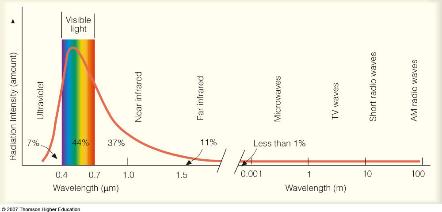
 

https://atmos.washington.edu/~hakim/101/radiation/ahrens_0208.jpg

Solar radiation spectrum

Source: Atmos Washington

Types of Panels

The theory explained before applies to all solar panels. Some differences are worth noticing among PV modules. Thus, we can classify solar panels by technology.

Monocrystalline

Monocrystalline solar panels are the top or premium type of PV module available in the market. These modules have the highest light to electrical energy conversion efficiency in the market, with values that range between 19-22% (for recent top brands). That is why they are considered in many PV applications, especially those with little space available for placing solar cells.


Due to this premium performance, they also have a higher cost.


These PV modules are also requested for RVs, cabins, and boats since they optimize the space available to generate the highest electrical energy output. In addition, they are used in many home-type applications because of their elegant black or dark blue color. Monocrystalline solar cells usually have a rounded shape edge that is created due to the manufacturing process.
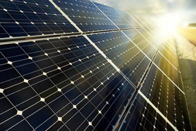
 

Resultado de imagen para monocrystalline solar panel

Monocrystalline solar panels

Source: Energy Global


The manufacturing of monocrystalline solar panels is done through the Czochralski method. This process consists of melting multiple silicon rocks at 2,500°F (1,371°C) and dipping a silicon crystal seed into this solution.


As the crystal is slowly pulled upwards, a crystal structure is created around the seed, commonly called an ingot. The ingot is made with a cylindrical shape (the reason for rounded edges) that is sliced into multiple silicon wafers that are later transformed into cells.


The steps of the process can be seen in the following figure:
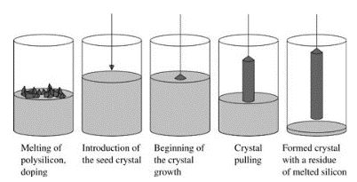
 

Czochralski manufacturing process for monocrystalline

Source: Top-alternative-energy-sources

Polycrystalline

The second option in terms of solar panel technology is the polycrystalline silicon module. These solar panels have lower efficiency values (between 16-19%) than monocrystalline modules. Still, their conversion efficiencies are good enough to be considered for the same applications as monocrystalline. Their most significant advantage when compared to monocrystalline technologies is their price.

The appearance of polycrystalline solar panels has a light blue color. Sometimes granular shapes can be visible on the surface of the module depending on the brand and year of manufacture. These modules look less elegant than monocrystalline technologies, which is why they are less requested when aesthetics is a must. Unlike monocrystalline panels, these modules have a squared shape edge.


Regarding the manufacturing process, these modules follow a similar procedure compared to monocrystalline.


However, an important difference is that instead of pulling out the silicon crystal from the molted silicon solution, it is cooled down. Then, the structure is sliced into multiple silicon wafers. The granular shape of some polycrystalline panels is because the ingot is created from various silicon rocks.
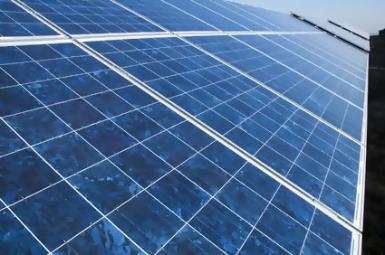
 

Resultado de imagen para polycrystalline solar panel

Polycrystalline solar panels

Source: Solar Advice


A 100W polycrystalline panel will be a bit bigger than a monocrystalline 100W panel. This is because polycrystalline has to account for lower efficiency. If space is a constraint, use monocrystalline. If space is not a constraint, use polycrystalline.

Thin-Film Technology

The thin-film solar panel technology is the third and last type of variation in the market. These modules are made of incredibly thin films that are nearly 20 times thinner than the typical silicon-based panel, a property that makes them flexible and lightweight. If encased within plastic materials, the cells are flexible enough to adapt to the roof’s shape surface.


Thin-film modules have an important advantage compared to other silicon-based solar panels, more related to market perspectives than to the technology itself.


In February 2018, President Donald Trump’s administration applied Section 201 Trade Remedy tariff of 30% on all silicon-based solar panels imported into the U.S. because they harmed local panel manufacturing. However, these tariffs apply only to monocrystalline- and polycrystalline-type technologies, not to thin-film modules. This adds in favor of the market share that thin-film technologies can have due to lower costs.


Back to technology types, thin-film modules can be divided into four possible types:


  • Amorphous-silicon (a-Si)
  • Cadmium-Telluride (CdTe)
  • Copper Indium Gallium Selenide (CIGS)
  • Organic Photovoltaic (OPV)

Amorphous Silicon (a-Si)

The oldest thin-film technology is amorphous silicon. This type of module has a wide range of light spectrum absorption and is manufactured with non-toxic materials. Typically, small gadgets like solar calculators, solar watches, and solar chargers for outdoors use a-Si cells because these devices need very low amounts of energy to work.


One of the most significant downsides of this technology is the efficiency values, which typically range between 10-13%, too low for residential or commercial applications. On the other hand, flexibility and cost are their biggest advantages.


The manufacturing process for these modules is different from its predecessors. Unlike polycrystalline or monocrystalline modules, amorphous solar panels are made from a thin plastic roll of 30 micros thick, passing through a metal deposition machine that places a thin layer of silicon material onto the plastic. Then another machine uses lasers to scribe the material intersections that define the individual solar cells.
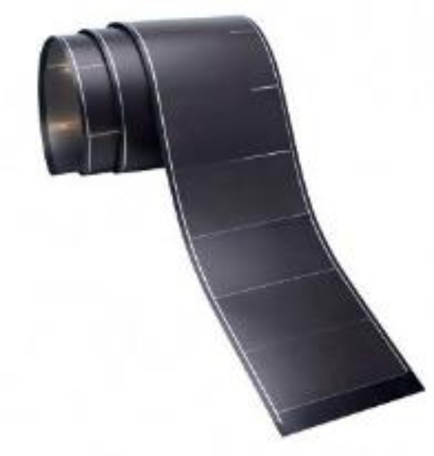
 

Imagen relacionada

Thin-film roll of solar panels

Source: Clean Energy Authority

Cadmium Telluride (CdTe)

The cadmium telluride is the most common type of thin-film technology that we can see in commercial applications. Here, the leading company is First Solar, which dominates the utility-scale sector. These modules' conversion efficiency values from First Solar can go from 15% (Series 4) up to 18% (Series 6), suitable for utility-scale applications.


CdTe modules are made from several thin layers, some for electricity generation and some for conduction and collection of electricity. They are typically applied over fixed supporting materials as monocrystalline modules.


CdTe panels have better efficiency values related to lower light wavelengths and can be manufactured at lower costs since cadmium is abundant as a byproduct of zinc. However, the main disadvantage of CdTe modules is pollution since cadmium is a highly toxic material.


Despite that using these modules in residential or commercial applications is not dangerous for human health, the recycling process of these panels is another thing.
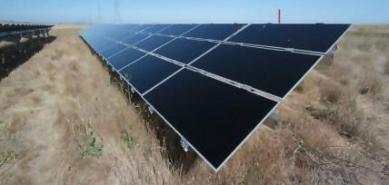
 

Resultado de imagen para first solar solar panel

First solar PV modules installed in a 40-MW power plant

Source: Renewables Now

Copper Indium Gallium Selenide (CIGS)

CIGS modules are generally produced through co-evaporation or co-deposition techniques. Copper, indium, gallium, and selenide are placed on the substrate (plastic, steel, glass, or aluminum) under different temperature rates and are sandwiched between conductive layers. When placed on a flexible backing, layers are thin enough to bend at the user's will up to a certain point.


CIGS module manufacturers such as Sunflare, MiaSolé, and Solar Frontier typically focus on covering markets that silicon-based technologies cannot cover. For instance, MiaSolé focused on commercial rooftop applications. However, they shifted the market sector to transportation and trucks. The purpose was to provide an environmentally friendly fuel consumption reduction solution.


They also manufacture flexible solar cells placed on a steel substrate with efficiency values reaching 17%. Their modules can be installed through a peel and stick system that makes them easier and cheaper to install on trucks, carports, or seismic areas. These properties make Sunflare, Solar Frontier, MiaSolé, and other CIGS module manufacturers ideal for RVs, vans, and boats where the surface could be curved.


The main disadvantage of CIGS modules, when compared to CdTe panels, is the price.

 

Sunflare flexible solar panels on a curved trailer

Source: Sunflare

Organic Photovoltaic (OPV)

The organic photovoltaic panel is made from conductive organic polymers that generate an electric current after depositing multiple layers of thin organic vapor between two electrodes.


These solar cells are ideal for new applications such as building-integrated photovoltaics (BIPV). Thanks to the ability of these cells, OPV panels can be colored in several ways or even be made transparent. This is perfect for BIPV applications, where color variation is an excellent addition to integrating solar panels into windows of buildings. Due to the abundance of organic polymer materials, manufacturing costs are low.


Organic solar cells are thin, flexible, and printable as well.


The main downside of this technology is efficiency since organic solar cells generally reach values close to 11%, well under the current standard of the market. Another issue is related to lifespan. Organic degradation does not occur in other technologies and reduces the number of years that the cells can efficiently work.

 

Resultado de imagen para organic solar panels in BIPV applications

Unique bus stop using organic solar cells

Source: PVinnovation

Other Cell Types

Gallium Arsenide (GaAs)

The Gallium Arsenide solar cell is another type that can be found in the market. These solar cells are the ones with the highest efficiency values.


Alta Devices, a GaAs solar cell manufacturer, has been able to bring a 29% efficient cell and promote it at the market level. It is known as the dual-junction cell. GaAs cells have other advantages: flexibility, lightweight, adjustability to multiple colors, thinner and malleable structure, good temperature resistance, and good performance under low light conditions.


Despite this high-efficiency value, GaAs cells have a significant disadvantage: high costs.


Since gallium is scarce and arsenic is toxic, the raw materials and the manufacturing process costs of these solar cells are much higher than traditional silicon-based technologies. This is why GaAs is used in very small applications where efficiency is crucial, like space aircraft applications. You are more likely to find GaAs solar cells than solar panels.

Dye-Sensitized

The dye-sensitized solar cell is based on a semiconductor generated between a photo-sensitized anode and an electrolyte. These cells are easy to manufacture through printing cell techniques. They are semi-transparent. Overall, conversion efficiency rates are close to 11%. These cells also work well under low light conditions.


Their main disadvantage is cost as well, which is why they are not used for residential, commercial, or large-scale power plants. As a result, this is the most forgotten solar cell in the market.

Perovskite

Finally, the ultimate type of solar cell technology is perovskite. Although not yet manufactured on a large scale, this technology is expected to revolutionize the solar panel manufacturing industry if it is successfully deployed in the next few years.


Efficiency values are expected to be at least 25% and may even reach 30%. In addition, low manufacturing costs, flexible, and printable make it an attractive option for future market development.

 

Printable perovskite solar cells

Source: Instyle Solar


Now that we talked about the different solar panels, we will go more in-depth about their characteristics, series and parallel, tilting, shading, and more.

Conversion Efficiency

The conversion efficiency of a solar panel represents the maximum power output that the module can provide based on a specific module size area. Therefore, a solar panel with higher efficiency needs less space to give the same power output.


The maximum theoretical value that a silicon solar panel (based on a single-junction structure) can achieve is the Shockley-Queisser limit and is 33.7%.


Higher efficiency values are linked to higher costs, implying fewer solar panels and space to reach the same energy needs.

I-V Curve

Since solar panels generate DC electricity, two parameters determine the power output of the PV module:


  • Voltage
  • Current

As you already know, voltage (V) multiplied by current (I) makes up the power (Watt) of a device.


As I will explain later, voltage and current parameters vary according to ambient conditions. The pattern change of these two parameters follows a specific curve. This curve aims to determine the equivalent power output for two voltage and current values provided.
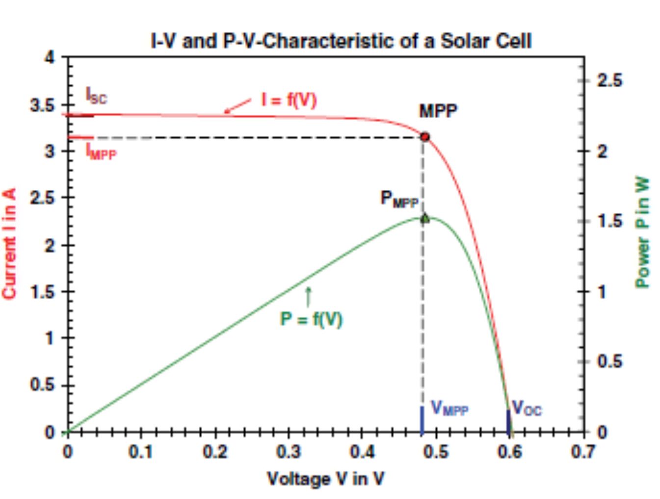
 

I-V curve of a solar cell

Source: H.Haberlin

“Photovoltaics — System Design and Practice”


If we look closer, there are two curves. The curve on top: I=f(V) represents the I-V curve that shows variations of current according to voltage values. The I-V curve shows multiple parameters that are worth noticing.

Voc and Isc

The first two that we must notice are the open-circuit voltage (Voc) and the short-circuit current (Isc). These parameters are located on the external points of the curve, and they represent the highest values that both voltage and current can have.
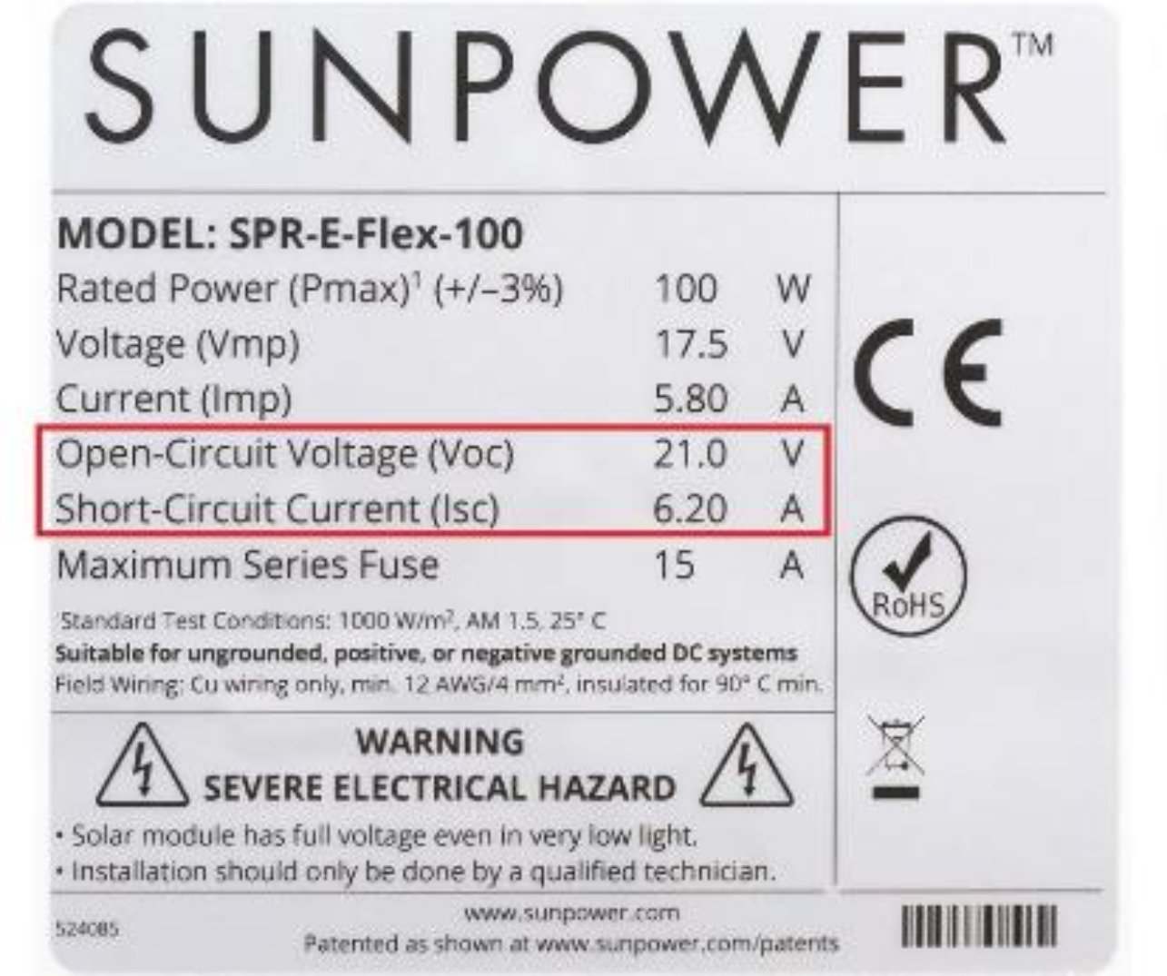
 

Specifications of a solar panel

Source: Sunpower


To understand how this curve works, we can position ourselves on the highest point of the curve, which is Isc. This point represents a short-circuit condition in which the solar panel is connected to a very low resistance (ideally zero) that allows electrical current to flow at maximum value. It would be equivalent to wire the positive and negative terminals of the panel together.


When the resistance is increased, the voltage starts rising. The current starts reducing step by step until resistance is too big to allow the current to flow, which leads to the open-circuit condition.


Under this condition, voltage is at its highest value (Voc), and the current is zero. This is equivalent to leaving the two terminals of the solar panel without connection to any load (here, the maximum resistance is the non-conductive air).

Impp, Vmpp, and Pmpp

The following two parameters on our list are the maximum power point current (Impp) and the maximum power point voltage (Vmpp). Sometimes Imp and Vmp are used, which are similar. These two points are linked directly to the fifth point of the curve, the maximum power point (Pmpp or simply MPP).


The MPP represents the maximum power output that the solar panel can provide for specific ambient conditions. Vmpp and Impp represent the corresponding voltage and current values (respectively) associated with the MPP point.



Calculating the Pmpp:



Pmpp, Vmpp, and Impp of a solar panel

P-V Curve

The curve on the bottom: P=f(V), is known as the P-V curve. It represents variations of power output with respect to voltage. Here the Pmpp (MPP) is the only point of interest. The linear relation between current and voltage can be seen until reaching MPP.

STC and NOCT

There are hundreds of solar panel manufacturers available on the market. Therefore, the solar industry needs a way to categorize and compare modules. This is done through a laboratory test under which all solar panels must be submitted to test their performance under the same conditions. These are known as the Standard Test Conditions (STC).


STC on a solar panel


The STC reference parameters used in lab tests are:


  • Irradiance: 1kW/m2
  • Temperature: 25°C (77°F)
  • Air Mass: 1.5AM

This temperature is referenced to the module's operating temperature (not ambient temperature). All parameters explained before in the I-V curve will be referenced to STC in the datasheet of the solar panels.


Another typical reference value is the NOCT, the acronym for Nominal Operating Cell Temperature. This standard uses parameters closer to the typical operation of the solar panel since STC conditions are often unreal. The temperature value that is stated in NOCT represents the temperature of the cell under the open-circuit condition and under the following circumstances:


  • Irradiance: 800W/m²
  • Wind Speed: 1 m/s
  • Ambient Temperature: 20°C (68°F)
  • The temperature on the surface of the panel: 45°C (113°F)
  • Mounting system: Open rack

As we can see, there is a difference between the ambient temperature and the cell's operating temperature. The NOCT temperature value will generally be between 45-48°C (113-118°F), depending on the manufacturer.

Effect of Insolation and Temperature

As we mentioned before, the I-V curve depends on ambient conditions, mainly on two of them: irradiance and temperature.


A higher irradiance (sunshine) means more solar radiation. Higher solar radiation also means more photons that reach the surface of the module, and therefore, more moving electrons. Since the displacement of electrons is linked to the flow of electric current, then more electrons moving means higher current. In other words, more solar irradiance means more current, and less irradiance means less current. The relationship between these two variables is proportional and linear.


Irradiance (sunshine) does not affect voltage.

On the other hand, the temperature is different. The effect of temperature affects all variables. However, the most important effect is on voltage. Unlike irradiance, the relationship between temperature and voltage is inversely proportional and logarithmical.


This means that when the temperature of the cell increases, the voltage reduces, while if temperature decreases, the voltage rises. The following figure shows a graph illustrating the effects of irradiance and temperature on current and voltage, respectively.

Effect of temperature on voltage (left)

Irradiance on current (right)

Source: A. Walker.

“Technologies and Project Delivery for Buildings”


On the left, we see that the solar cell's voltage decreases with increasing temperatures while the current stays the same.


On the right, we see that the current decreases once less irradiance (sunshine) reaches the panel while the voltage stays the same.


Ambient Temperature and Cell Temperature

The cell temperature increases according to two factors:


  • The amount of current flowing through the cell.
  • The ambient temperature.

The first one depends on the load that the solar panel is connected to and the irradiance levels. When current flows through any conductor, an ohmic loss effect is created, which translates into heat. The same happens inside the solar cell. The second factor is dependent on the location where the panel will be installed.


As you can imagine, hot ambient temperatures will add a thermal effect to the module. Therefore, increasing the temperature of the cell. This is an undesirable condition as excessive temperatures decrease voltage and thus, reduce the power output of the modules.


On the contrary, low ambient temperatures favor the thermal cooling of the cell due to ohmic effects. Therefore, cool temperature locations are always desirable for solar panels.


Ironically, many locations with excellent solar irradiance also have high temperatures that translate into thermal losses (one of the most important photovoltaic losses). Therefore, in some cases, a location with a cooler ambient temperature and lower solar irradiance could be better for solar since thermal losses will be lower. You can increase the cooling effect by mounting your solar panels on a ground mount where circulating air can cool the panels.

Temperature Effects on Efficiency

As stated before, temperature affects the solar panel power output. As we have mentioned in the conversion efficiency section, the solar panel's efficiency depends on the Pmpp. Therefore, temperature intrinsically affects the efficiency of the solar panel as well. The relationship of this effect is linear, as can be seen in the following figure. This is an example of a solar panel with an efficiency of 14.8% under STC 25°C (77°F).
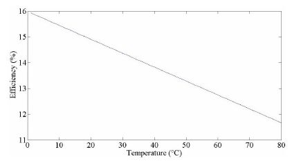
 

Efficiency variations according to temperature changes.

Source: "The Effect of Temperature on Cell Efficiency"


We can see that the efficiency drastically decreases if the temperature increases. Therefore, your solar panels must get as much ventilation as possible.

Series and Parallel Connections

Solar panels have specific power outputs in their datasheets. Despite new models that can reach values close to 400Wp, this power output is not enough to cover the energy needs of household appliances or bigger systems. Therefore, solar panels need to be combined to increase the power output.


Series connections are the same as batteries and consist of connecting the negative terminal with the positive terminal of the next solar panel.


Meanwhile, solar panels connected in parallel consist of combining the positive terminals and the negative terminals in the combiner box or by using branch connectors.


A set of solar panels connected in series is known as a string. A mix between solar panels in series and parallel connections is known as an array.


When solar panels are wired in series, the voltage of each module is added while the current stays the same. For instance, if the solar panel’s output is 10V and 1A, and you connect three modules in series, then the system's output will be 30V and 1A.


On the other hand, when solar panels are wired in parallel, current increases while voltage stays the same. So, based on the same example, if you connect three solar panels in parallel, then the system's output would be 10V and 3A.


When multiplying the voltage by current, both systems will provide 30W.


Higher current values translate into bigger gauges for PV wires. Therefore, series connections are preferred when connecting solar panels.


As a general rule of thumb, solar panels must be wired in series until the accumulated voltage is right under the maximum input voltage of your charge controller. The following example is a 3S setup (3 panels in series).
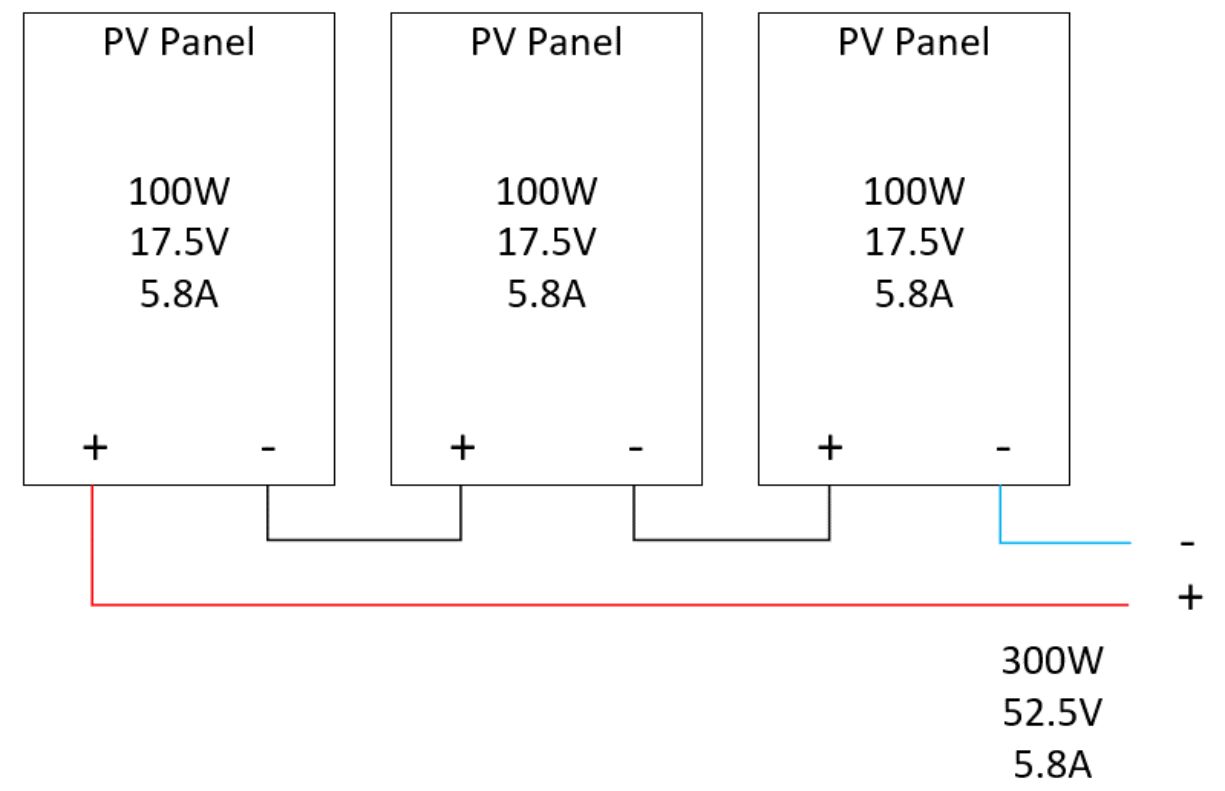
 

Series wiring of solar panels (3S)


The following example is a parallel connection. This setup is called 3P (3 panels in parallel).
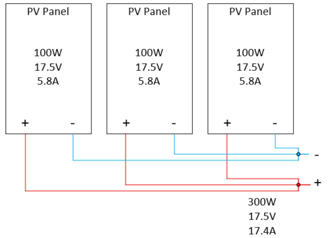
 

Parallel wiring of solar panels (3P)


Placing your panels in series or parallel will depend on the charge controller you will use. A PWM charge controller will only take as close to 12 or 24 Volts as possible. An MPPT can take voltages up to 100 Volts or more.


As you will learn later in the book, PWM charge controllers are cheaper than MPPT. If you wire your panels in series, the voltage will increase while the current stays the same. This will influence the diameter of your wire. The money you save on wiring in series instead of parallel can be spent on a more efficient MPPT inverter.


Another point to consider is the angle of the sun in the morning and the evening. Because of the low angle, your panels won’t generate as much voltage (low irradiance). If you wire three panels in parallel and each one of them generates 5 Volts, you will send 5 Volts to your charge controller, which won’t be enough to charge batteries (under the minimum required input voltage).


If you wire the same panels in series, you have 15 Volts (5V+5V+5V=15Volts), which can start to charge a 12V battery early in the morning or late in the evening.

Wiring Different Solar Panels

Another important rule that must be considered is that solar panels with different specs must never be wired together. Once you have selected a solar panel, you must purchase all the required modules for the PV system with that specific model.


You cannot wire solar panels with different specs because the PV system will not work optimally. The current output must be the same throughout the entire system in the series connection.

If four solar panels are wired in series, and one solar panel’s output is 2A while the others are 3A, the connection will only provide 2A.


The solar panel with lower output would not be capable of providing 3A. Therefore, the system must adjust and deliver 2A. This translates into underusing the capacity of the other solar panel(s). A similar problem occurs with parallel connections but with voltage.


If you have no other choice, and you must connect mismatched panels, use this rule:


  • Panels with the same voltage: wire in parallel.
  • Panels with the same current: wire in series.

Solar Panel Array

When making series and parallel connections, another factor should be considered.


Let’s say you have 8 solar panels, and the maximum number of modules that can be connected in series is 5 due to charge controller voltage input restrictions.


Now, you may think you could make a string of 5 solar panels and another string of 3 modules, connect the outputs in parallel, and wire it to the charge controller. However, this would be incorrect for two reasons.


The first reason is that the weaker string will have a lower voltage. This is because current always flows from the highest voltage point to the lowest voltage point.


This principle will generate an effect in which the other strings try to make the current flow toward the weaker string. This is highly undesirable since it can lead to malfunctioning and be devastating under short-circuit conditions.


The second reason is related to energy losses. As will be explained later, the charge controller must accurately find the MPP of the solar panels every time to operate optimally. If strings of different voltages are connected in parallel, then the I-V curve would lose its regular shape, and it would make tracking of the MPP very hard for the charge controller. This would end up in tremendous mismatch losses due to voltage differences. This will be explained with further details in the charge controller chapter.


Therefore, going back to our example, if you have 8 solar panels, you would have to size 4 modules in series (string) and put them parallel to become an array. We call this system a 4S2P (4 panels in series with 2 parallel groups).
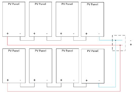
 

Diagram  Description automatically generated

Two series strings connected in parallel to the combiner box (4S2P)


If the charge controller only allowed for 3 modules in series, you would have to either work with 6 panels or add an extra solar panel to have 9 modules in total, of which 3 are in series. This setup is called 3S3P (3 panels in series and 3 parallel groups).


As previously mentioned, make sure the current flowing in the array is suitable for the wire according to the ampacity and the voltage drop. Refer back to the wiring section to learn how to calculate both.

Azimuth

The azimuth angle is referred to the direction of solar panels regarding the sun’s orientation. Solar panels must face south to harness the maximum power output for locations in the Earth's northern hemisphere. Locations in the southern hemisphere, solar panels should face North. Locations near the equator should face the panels almost horizontally.


For U.S. cases, a solar panel should take south as reference 0°. If you install solar panels on RVs or boats, it makes little sense to determine the azimuth angle since the solar panels will vary their azimuth as they go on the road or sea. Also, if solar panels are mounted to the RV roof in a flat position, it makes no sense to worry about that either.


If the solar panels you have installed can be lifted with a certain tilt for maximum solar power harnessing once you park the RV, then parking the RV so that the solar panels would face 0° south (or as close as possible) would be beneficial.


If you have a portable solar panel, finding the optimum azimuth angle will be beneficial. For this, you must simply use a compass and place the panels facing the south directly if you are not planning on moving the panels throughout the day.


Alternative azimuth directions are east or west, either one of them. Panels should never point north if you are in the northern hemisphere.

Tilt Angle

The tilt angle is another important factor in solar power harnessing. Finding the optimal tilt angle is always related to the latitude of the location.
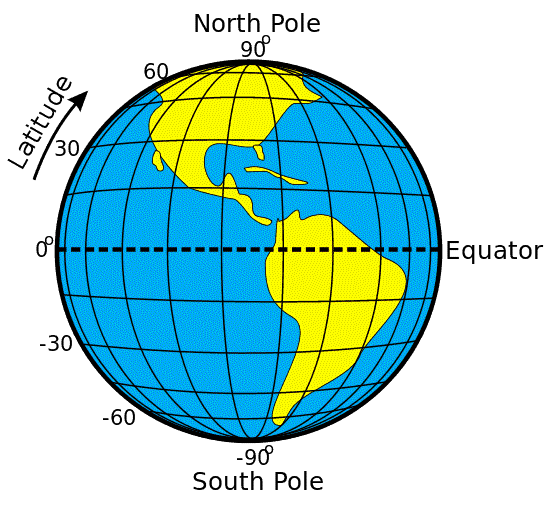
 

Image result for latitude

Displaying latitude

Source: Geography Realm


Most of the time, for locations near the Equator, choosing the latitude as the reference is usually the best approach.


Besides the location, another important factor that must be considered before setting the optimum tilt angle is the type of system that will be implemented. Also, since the altitude and direction of the sun vary according to the season, it is important to know when the system will be used mostly.


In grid-tied PV systems, the idea is to optimize solar power harnessing to generate as much energy as possible. Therefore, since solar power is generally higher during the summer months, then the PV system angle is optimized to harness as much energy as possible during summer. To calculate the optimum tilt angle under these conditions, you must apply the following expression:



Where will be the optimum tilt angle and will be the latitude of the location.


Example for New York in summer:



For stand-alone PV systems, the priority is not harnessing as much energy as possible but always being able to cover the system's power needs to provide stability. Therefore, the critical season under which the PV system must be optimized is no longer summer but winter. For these cases, it is advisable to use the following expression.



Example for New York in winter:



Figuring out the best tilt during the whole year:



Here is how you can find out the latitude of your location:


Go to google maps and click on the location you would like to know the latitude. The first numbers are the latitude. The one after it is the longitude. In this example, the latitude is 32°.
 

Figuring out the latitude of your location


Nevertheless, in RV and cabin applications, there is a particular consideration. Even though RV solar power systems are stand-alone based, RVs are not generally used for traveling during the winter season.


In other words, you must evaluate if you are using your RV only for recreational purposes during some time in the year (mainly summer for vacations) or if you are living in an RV throughout the year. If your case is the first option, you must use the expression to optimize the summer tilt angle. If your case is the second option, you must use the second expression. This is only applicable if you can tilt your solar panels.

Shading

Shading losses are one of the most underestimated factors in any PV system and must always be considered. There are mainly two types of shading: near-shading and far-shading.


Far-shading is associated with losses in diffused irradiance caused by mountains or high buildings. Unfortunately, there is not much that can be done about them.


On the other hand, near-shading is associated with nearby objects that can project shades over the solar panels. For example, things such as trees, walls, antennas, or the air vent of the RV can create shade on the solar panel.


When a solar panel is shaded, the current output of the module is affected since the obstruction represents a reduction in the number of photons that the module can absorb. In addition, the power output of the entire string of the shaded solar panel is affected as well because the electrical current that flows through a string (series connection) must be the same in every module.


If you remember the effects of solar irradiance (Watts/m²), you will know that it affects the current, and the temperature affects the voltage. So, if you were to shade one panel in a string, only the panel with the lowest current would decide the power output.


This can be seen in the next image.
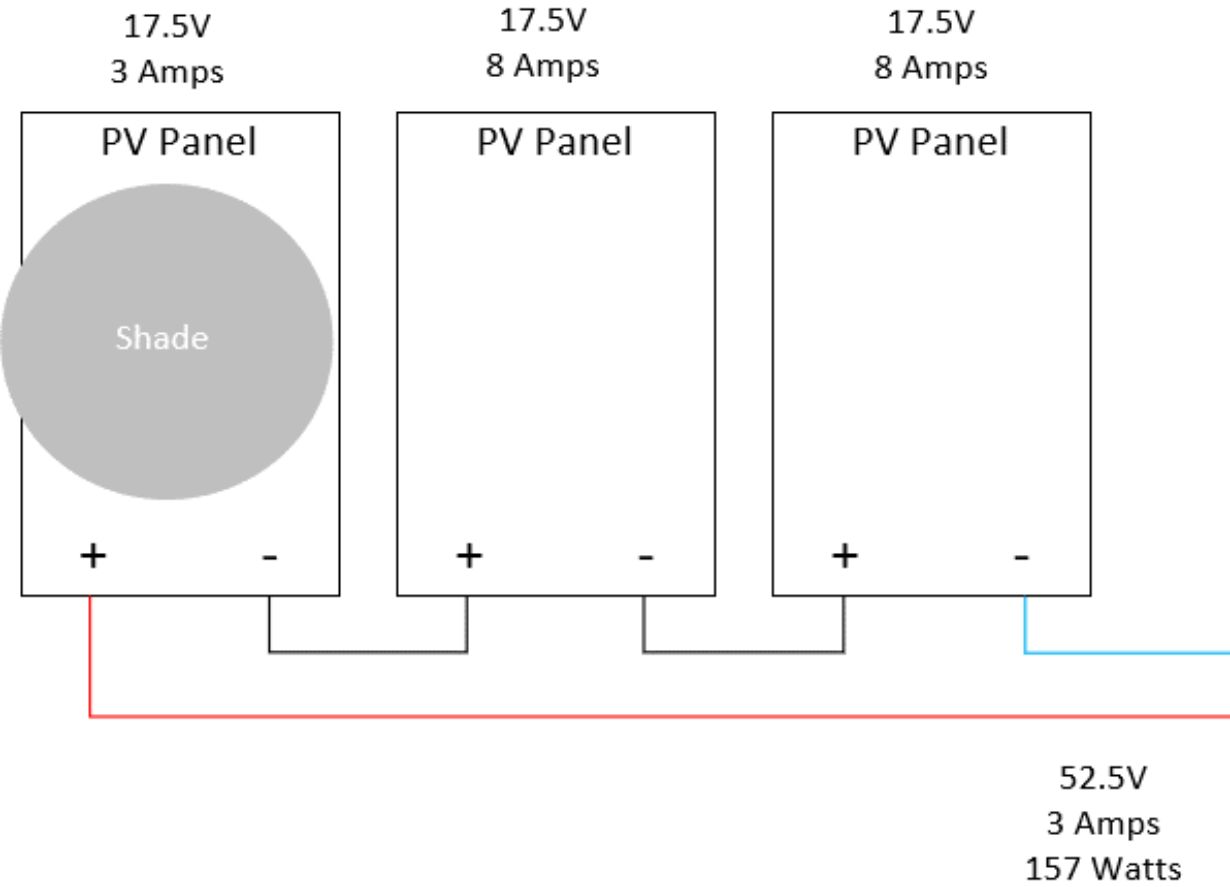
 

Effect of shading on series connections


The electrical current can only be as high as the current generated by the weakest module (shaded module in this case). Therefore, the output of this string is only 3 Amps.


To account for solar power losses due to shadings, solar designers use simulation software that calculates the projection of the shade across the day and its impact on the PV system.


You should try to avoid any near-shading that could cause essential power losses to your PV system.


Another useful technique that is used to deal with shading is the position of the module. If the power production were to be reduced by a small partial shading in the corner of the module, it would be a very inefficient generation source.


Solar panel manufacturers install bypass diodes in a box located in the back of the module, known as the junction box. If the solar panel is partially shaded, these bypass diodes allow electric current circulation from the other sides of the module.

This means the reduction in power output due to shading will not be total but partial. The following figure shows the structure division of a Panasonic solar panel with 4 bypass diodes. When a leaf partially shades one section, the bypass diode of that section activates to allow current circulation from the remaining solar cells. Most solar panels generally have 3 bypass diodes in residential and commercial applications.
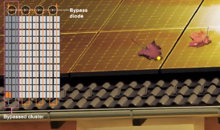
 

Bypass diodes in solar panels

Source: Panasonic HIT module brochure


The trick lies in using this property of solar panels in favor of shading. By placing the module vertically or horizontally, the effect of shading can be very different.


Most modern panels have these bypass diodes. Check the datasheet of the panel to make sure they have bypass diodes before buying the modules.


If your solar panels are parallel and one is shaded, the rest will feed back into the shaded panel. The shaded panel will consume a small current, which is called back-feeding. To remedy this, you could use a blocking diode. A normal diode, or a Schottky diode, will have a voltage drop which is not desirable. Instead, use an ‘ideal diode.’ These diodes have a very low voltage drop.
 

Ideal diode


If you are on a sailboat and you are sure to expect shade from the sails or boom, it is recommended to use parallel connections with an ideal diode to prevent back-feeding into other panels. Most solar panels already have a back-feeding diode installed. Make sure you check the datasheet of the panel. You can also use two separate charge controllers.


In the following diagram, you can see the effect of shading on parallel connections. If you compare this to the series connection, we can see a higher power output. This is because, in parallel, the amps are added together while the voltage stays the same. Again, because the sunshine has an effect on the current, the voltage stays the same.
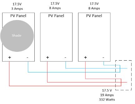
 

Effect of shading on parallel connections


We can see that three 140 Watt panels in parallel will have a combined output of 332 watts instead of 420 watts. If we have the same setup in series, the output power would be 157 watts.


The downside with parallel connections is that you need to have a bigger wire diameter to handle the increased current.


To sum up, if you expect shade, it’s best to wire in parallel. If you do not expect shading, wire the panels in series. Always choose a location without shading throughout the day. If your panels are ground mount, have at least one foot of clearance from the base of the panel to the ground.

Hotspots

You already learned that shading a panel will reduce its output. The energy that is lost will be dissipated as heat. This will create a hotspot on your panel. A hotspot is where the shaded cells dissipate the heat. If the hotspot is there for a long time without cleaning the panel, it can lead to permanent damage and reduced panel output.


Causes of hotspots can be bird droppings, dust on the panel, or the shade of a plant. Hotspots can be detected with a thermal imaging camera.
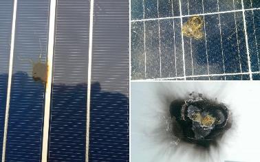
 

Solar Panel Hot Spot Exposed! Solar Review.

Examples of hotspots

Source: review.solar


It is essential to avoid shading on a solar panel at all costs. This will reduce output drastically. Periodically clean your panels because the accumulated dust will reduce the power output. More about the effects of cleaning your panels later.


Blocking Diodes

Blocking diodes are sometimes used in battery-based applications that involve solar panels.


The current flow in any electrical system always goes from the highest to the lowest voltage point. Keeping that statement in mind, during the day, solar panels have higher voltages than batteries. Therefore, voltage naturally flows toward the battery to charge it.


During the night, there is no sunlight, and solar panels generate no power at all.


The battery will never be discharged entirely (or at least it shouldn’t). As the only source of power in the PV system, the battery will provide electrical current to any other device. The electrical current could flow back to the solar panels during this time, making you lose energy.


When charge controllers did not exist, installers needed to add a blocking diode between the module and battery to avoid this reverse current effect.


Nowadays, manufacturers take care of this element by adding what is known as a Schottky diode, which combines the functions of both blocking and bypass diodes. These diodes are already integrated into the charge controller.

Fusing Solar Panels

A short-circuit condition in solar panels can occur due to metal-to-metal contact of the PV wires in one of the strings due to a mechanical accident or lightning. Under this condition, the faulted string would receive the short-circuit current from every string of solar panels known as the reverse current.
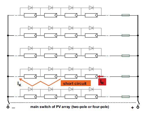
 

Short-circuit condition for a 5 strings PV system

Source: H.Haberlin

“Photovoltaics - System Design and Practice”


As shown in this image, in a PV system with 5 strings of modules (4S5P), the total short-circuit reverse current the faulted string could receive, will be four times the short-circuit current of the module (close to 9A). In this case, the faulted string would receive a 36A short-circuit current. This would be destructive for both the modules and possibly the wires and could even induce fire.

Solar panel strings should be protected against high reverse currents that can damage the modules and the PV wires under a short-circuit condition.


To protect the PV modules, DC compatible fuses are installed on the positive side terminal of each string. DC fuses act as overcurrent protection devices that will isolate the faulted circuit from the rest by melting down a conductive material inside the fuse when a specific current passes through the fuse.


These fuses are generally installed with an inline MC-4 connector or in a DC combiner box.


To select the string fuse, two factors must be considered:


  • The open-circuit voltage of the module.
  • The short-circuit current of the module.

It is crucial to size the string fuse for both factors. Only sizing the fuse as short-circuit protection would be unsuitable and could even cause malfunction and fire.


Since the DC signal never crosses through zero volts, safely isolating the circuit from the rest is much harder than with AC power. Therefore, you must ensure that the fuse you select has been designed for DC connections to interrupt the current flow safely.


Under specific weather conditions, solar irradiance values could be close to 1,000W/m2, which will cause additional stress to the fuses due to increased heat. Moreover, the fuse could be submitted to this stress with an additional rated maximum current flow through it, which will increase the heat inside the fuse.


Assuming these conditions, it is recommended to apply security factors to size the fuse. A 25% security factor should be used due to excess irradiance, and another 25% due to 3 continuous hours of operation under these conditions. Based on these considerations, the rated current for the DC fuse should be calculated as demonstrated in the following expression.



On the other hand, considering the open voltage of the modules, string fuses should be rated for 1.2 times the STC open-circuit voltage of the entire string. This voltage can be calculated by verifying the open-circuit voltage of the module model and multiplying it by the number of solar panels (nsp) in every string. The result should be your minimum voltage to the DC fuse or breaker.




Let’s explain this with an example. Three panels in series with the following specifications:
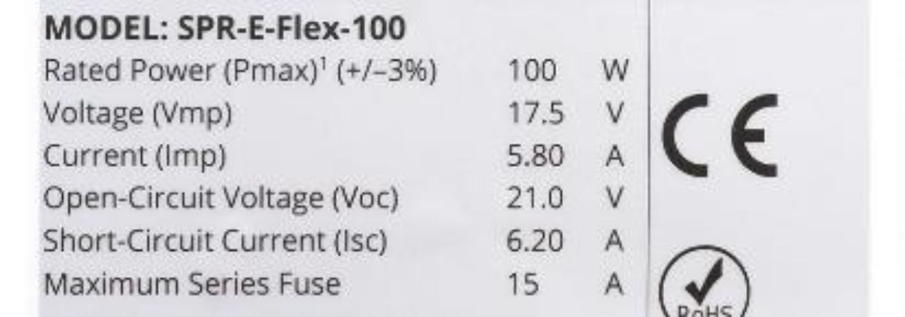


Minimum current for the fuse:



You can see on the solar panel specifications that the maximum fuse in series is 15A. Do not go higher than the recommended fuse by the manufacturer. You can either use a 10 Amp fuse or a 15 Amp fuse.


Minimum voltage for the fuse:



DC fuses are rated for a specific voltage. Choose a DC fuse that can handle at least 75.6 Volts.

Series Connection

For series connections, You only need to use one fuse for each string. You can use an inline MC-4 connector fuse. Using an MC-4 connector fuse is recommended because you won’t have a combiner box with series connections. If you have multiple series strings coming together in a combiner box, you can use the classic fuse holder in a combiner box.
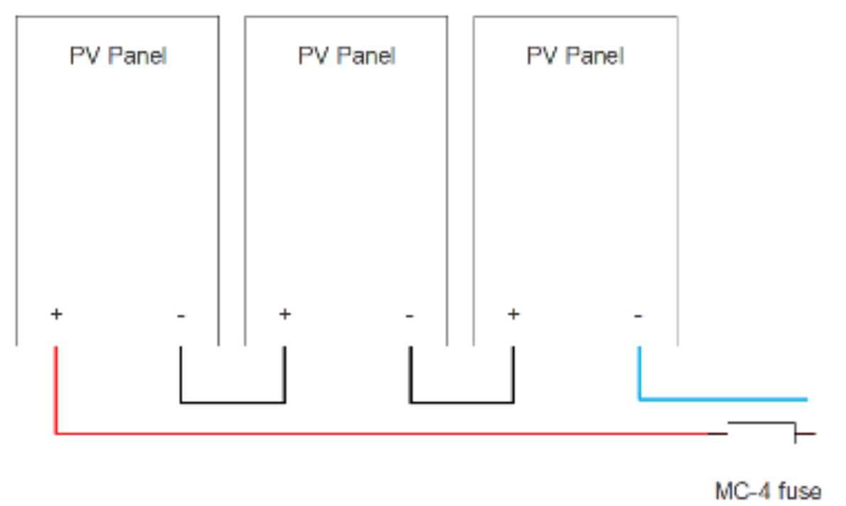
 

Using fuses in series connections
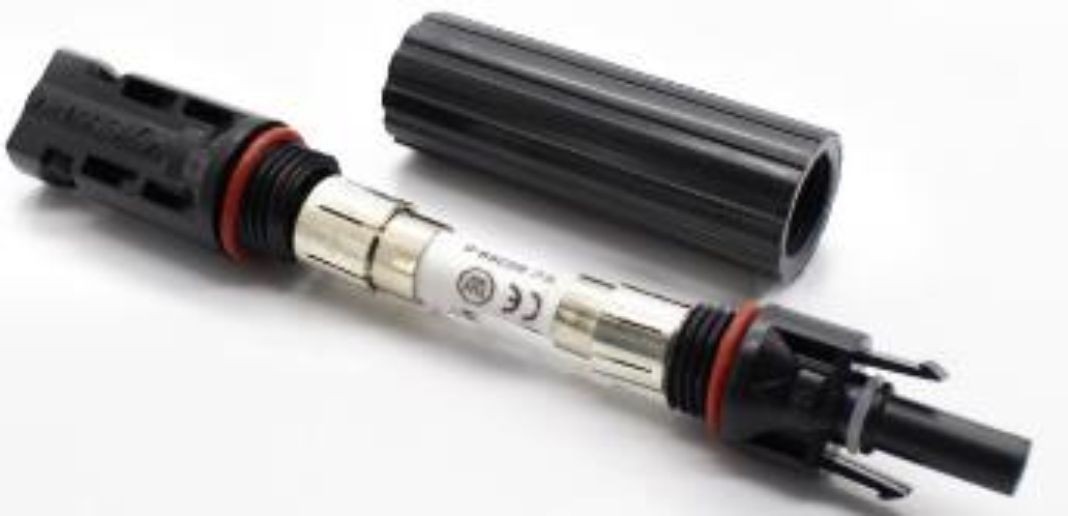
 

Example of an inline MC-4 connector fuse

Parallel Connection

You can use inline fuses for parallel connections too. However, most parallel systems use a combiner box. Combiner boxes combine multiple wires into one wire that goes to the charge controller. Wiring fuses this way can be cheaper than buying inline MC-4 fuses because you will need the combiner box anyway.
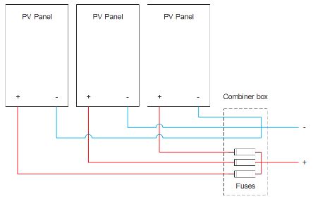
 

Wiring fuses in parallel connection


In parallel connection, you need to fuse every series string. If you have 8 panels and configure them in a 4S2P setup, you have to use two fuses. One fuse for every series string. One fuse will protect 4 panels because the current in a series string is the same.

Seasons and Solar Map

The solar radiation in the U.S. varies according to the year's seasons. Spring and summer are excellent seasons for solar.


Solar radiation also changes according to location. Before entering into further details, there are three terms that you should be familiar with:


  • DNI
  • DHI
  • GHI

DNI stands for direct normal irradiance, referred to as the irradiance [W/m2] that touches the surface of the modules at a perpendicular angle.


Diffused horizontal irradiance (DHI) is another term used to refer to the radiation reflected or absorbed by the clouds and any other surface.


The global horizontal irradiance (GHI) represents the combination of these two components and is the effective irradiance used for solar energy yields.


As can be seen in the following image, the (GHI) across the U.S. changes between 4-6 kWh/m2/day, whereas the northern states such as New York, Michigan, and Pennsylvania generally have less irradiation available.


Variations in solar radiation according to the seasons can be visualized with the U.S. Solar Radiation Resource Maps.


Keep in mind that from a grid-tied or backup perspective, going solar does not only depend on the solar radiation that is available in the location. It is also dependent on the electricity rate that is associated with your energy bill. From an RV perspective, the solar radiation of your location is even more relevant since the PV system needs to work on its own every day under off-grid mode. When you are sizing your system, you must consider the locations through which you are moving.


Looking at a U.S. Solar Radiation Resource Map will give you a good idea of the estimated irradiance value in your location. Keep in mind that this is related to GHI, not to direct normal irradiance (DNI).

 

Solar Irradiance Map of the U.S.

Source: NREL


To see an interactive map go to:

https://cleversolarpower.com/solar-irradiance

Placement of panels

When installing solar panels, you will always have two options if the system is intended for residential applications.


The first option will be to install solar panels on your roof. The second option is to use ground-mounting.


There is a set of advantages that you will have by choosing a ground-mounting installation. Orientation and tilt angle variability is much wider with ground-mounting than with roof-type. Also, maintenance procedures are easier since the modules are placed in an accessible location for the homeowner. It is very important to clean the modules of any dirt or snow.

These systems have a better cooling system since air circulation on the backside is better than roof mounting. You won’t need to make any modifications to your house to install the modules, and from an expansion perspective, ground mounts are much easier to expand.


On the negative side, ground-mounts are generally more affected by shade than roof-mount types since more objects can project shade over the modules. Besides, the installation procedure is often more complicated than the roof-mount and probably more expensive. Finally, another important point is that you will reduce space in your backyard that could be used for recreational purposes.


If you choose to go with roof-mount to your home, you will have many benefits. Among them, installation costs will be lower (unless your roof requires structural updates).

The solar panels can also protect your roof surface from hailstorms and any falling object since they are made to resist impacts (to a degree). The low accessibility to your solar panels may be bad on one side from a maintenance perspective. However, from a security perspective, your solar panels could rarely be damaged, stolen, or even vandalized since they are located on the roof.


Meanwhile, by installing a roof-type solar system, you will need to take care of several details. Things such as roof penetration during the installation, maintenance, limitations on system size due to space availability, and roof structure upgrades if needed to hold the weight of the modules.


Based on these pros and cons, you will need to make a balance and decide on where it is better to place your solar panels, either on the roof or on the ground.

Mounting Panels

The procedure for mounting the modules depends on the type of mounting system you would like to use.

Roof-Mount

For roof-mounting systems, the following procedure must be followed:


  1. You need to have your equipment and materials — drilling, pencils, chalk blocks, rails, clamps, bolts, and screws.
  2. Calculate the distance between rails on the roof based on the pre-drilled holes of the solar panels.
  3. Check the required setbacks for rooftops. Generally, 3 feet is an acceptable setback.
  4. Locate the roof's rafters to center the truss that will be the supporting spot for the rails.
  5. Install flashings (supporting structures that tighten the modules to the roof).
  6. Place the rails.
  7. Add grounding bolts and wire management clips.
  8. Secure the modules to the mounting system by using clamps and T-bolts.
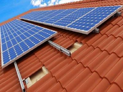
 

Image result for roof mount solar panel

Solar panels mounted on rails

Source: FOEN solar bracket

Ground-Mount

For ground-mounting systems, the steps for the installation are as follows:


  1. Excavating the ground to provide enough space for foundations. The type of foundation depends on the soil type in your area.
  2. Concrete foundation or helical piles are installed.
  3. The base of the mounting system is fixed to the foundations by using bolts.
  4. Vertical pipes are installed and fixed to the base of the mounting system.
  5. Rails are installed and attached to the structure. Unistrut or unirac are both great materials to work with.
  6. Cross rails are installed if needed to provide additional support for the structure.
  7. Middle and end clamps are used to adjust the solar panels to the rails.
  8. A tilting mechanism can be installed for summer or winter.
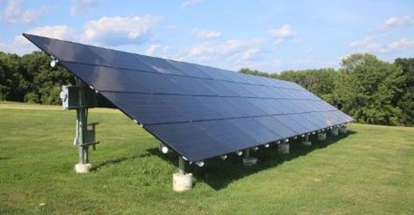
https://upload.wikimedia.org/wikipedia/commons/thumb/9/95/Ground_mounted_solar_panels.gk.jpg/640px-Ground_mounted_solar_panels.gk.jpg

Ground-mounted solar panels

Source: Wikimedia.org

RV’s

RV solar panel systems have another installation process, similar to roof mount, but not equal. The process is briefly explained as follows:


  1. Organize the available space on the roof and make a schematic of the distribution of panels on the rooftop.
  2. While still having the solar panels on the ground, install the mounting brackets. This will save you additional work on the roof.
  3. Make the setup process for the charge controller and batteries. From a roof perspective, figure the shortest path to take the wires from the roof to the charge controller’s location.
  4. Drill a hole through your roof to pass the wires.
  5. Install a waterproof cable entry plate in the position of the hole to pass the wire output of the solar panels.
  6. Drill the corresponding holes to secure every module according to the pre-drilled hole positions located in the mounting frame of every module.
  7. Secure them to the roof by using bolts and screws together with silicone to make it waterproof.

There are many different types of mounting solar panels to the roof of your RV. Some people prefer not to drill in their roof and use brackets to stick the panels to the roof.
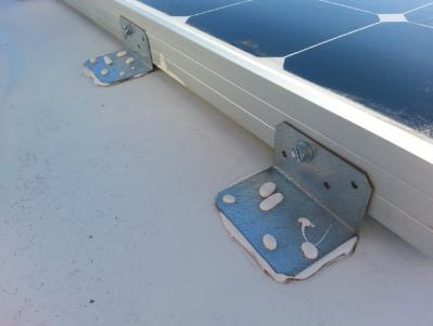
 

Image result for rv mount solar panel

Mounting solar panels on RV roof with brackets

Source: JdFinley.com


Items used for mounting:


  • 90° brackets from your hardware store.
  • 3M 5200 adhesive (no sealant) or VHB tape.

If you have selected flexible, thin solar panels, the installation is easier since you can use strong double-sided tape to adhere the panels to the roof.


All vehicles are designed to be aerodynamic. This means reducing air friction during traveling. If the vehicle is not streamlined, noise will be created, which you will hear when driving the vehicle at high speeds. Therefore, try to reduce air friction as much as possible.


Because of the air friction, the solar panels could come loose, which you do not want to happen when you are driving. Therefore, it’s best to link all your panels together with a steel cable. Then, if one panel comes loose, it won’t fly away and damage something or hurt someone. Also, periodically check your roof for any loose mounts.
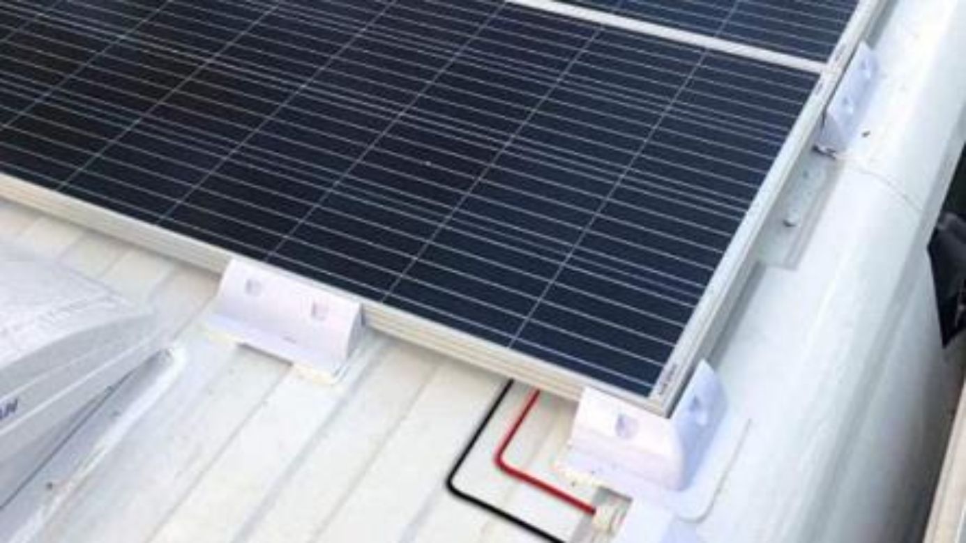
 

Drill free solar panel mounts

Sailboats

In the case of sailboats, the procedure is similar to RVs. You will need to use a boat Bimini cover to place the modules most of the time. The flexible solar panels are used much more for boat applications since drilling holes in the bow or the stern is something that you are probably not going to like. When you have sized your Bimini cover, you will need to find similar suction cups or plastic attachments that can go through the holes of the panels and lock them in place.


Stitching a flexible solar panel to the Bimini cover is a popular method. Instead of using the suction cups at the corners, you install a special cloth that you can stitch to the bimini.
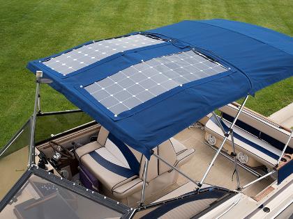
 

Flexible solar panels installed on a bimini top

Installing solar panels on a Bimini

Source: www.sailrite.com

Cleaning Panels

The Effect of Soiling

Maintenance is an important factor that must be considered when installing solar panels. The performance of PV modules can be severely affected by dirt or dust on the surface of the panels. In most cases, with regular maintenance procedures, this PV energy loss (commonly called soiling) should not be higher than 2% of the annual energy yields.


Extreme cases with considerable dust and no cleaning can reduce the modules' performance up to 30%.


The following image shows a graph with the differences in the I-V curve and the MPP before and after the cleaning procedure for a small PV system. As you can see, the power output is reduced from 3kW to 2.15kW, which is a significant power output reduction and why it is so important to clean your solar panels regularly.
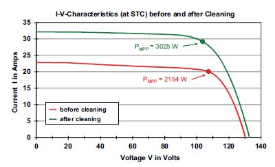
 

I-V curve after and before cleaning

Source: Haberlin Heinrich.

“Photovoltaics System Design and Practice”

How to Clean Your Solar Panels?

The cleaning procedure for solar panels is straightforward. The first thing that must be done is disconnect the PV system by turning off the solar disconnect switch. This is for safety concerns.


Then, you need to get a sponge and submerge it in preferably de-ionized water. Avoid regular water for cleaning since the minerals contained inside will adhere to the module's glass.

Try to avoid using cold water or hot water to do the cleaning. High-temperature differences are not good for the modules. Using the sponge, start cleaning each module until any noticeable dirt is cleaned up.


Soft brushes can also be used. Telescopic cleaning poles will make it easier for you to clean your modules if they are located in inaccessible spots. Another option is to use a low-pressure hose to clean the modules. Pressure should always be under 580psi (40bar).


Never use laundry detergents, bleach, or any other product. All that needs to be used is distilled water, and if desired, a little bit of dishwashing soap. You can also use specially designed solar cleaning equipment to make the task easier.

When to Clean Your Solar Panels?

The time to clean solar panels is important. During noon, solar panels are producing electricity at peak performance. Choosing to do maintenance during this period is not good for two reasons. First, if you do cleaning at this time, you will lose the most important energy yields of the day, and second, at noon, solar panels are hot. This makes them difficult to clean.


Solar panels can reach temperatures of over 158°F (70ºC). The ideal time for cleaning is during the early morning or late afternoon. At these times, solar panels’ performance is lower, and they are much cooler.

Solar Panel Lifespan

The lifespan of a solar panel is widely dependent on the brand and model type. However, currently in the industry, most rigid solar panels feature a 25-year life warranty performance.


It is important to notice that this is not the same as the product warranty (which is generally close to 10 years), but it is an estimated life expectancy of the solar panel production. The warranty performance states how many years the solar panels are expected to work and produce with at least 80% of their power output in the initial year.


The best solar panels available can reach almost 30 years of performance and have a 15-year product warranty. You can find the life warranty performance in the datasheet of the module.

Panel Voltage

As we have discussed in previous sections, the current flow goes from high to low voltage. Solar panels are designed to be a generation source. Therefore, they must have a higher voltage than the load itself.


In battery-based applications, the solar panels must be able to charge a battery bank. For instance, in case of a 6V battery, you would need a solar panel with a voltage output of at least 6.75V. Moreover, assuming that the battery has a 12V nominal voltage, then the modules need to charge that battery with a higher voltage (at least 13.6V).


If the battery bank voltage is 24V, then you would need to wire solar panels in series to achieve a higher voltage (at least 27V). However, some bigger solar panels are already able to reach 30-40V.


Keep in mind that the key factor in reaching the required voltage levels lies in adding as many solar panels in series as your MPPT charge controller is designed for (usually 100Volts).

Buying Used Solar Panels

Solar panel installers will always provide you with new PV modules. However, on some occasions, you will find available modules on the web set for sale at lower prices, but they are used.


Purchasing used solar panels for residential or commercial installations presents multiple problems that far outweigh the possible economic benefits.


Used solar panels can be on sale for different purposes, but mainly there are two reasons:


  • First, the homeowner no longer wants to use all the panels for his/her PV system and wants to get some money back.
  • Second, the solar panels suffered some sort of damage, or their performance is not what was expected from them.


This can be a serious problem if you choose to purchase multiple used solar panels since you can end up investing a substantial amount of money and not receive the expected performance. Solar panels also degrade over time, and it is hard to precisely estimate the number of years that the solar panel has been working. Reduction in performance would be hard to determine if it’s related to aging, damage, or manufacturing failures.


Used solar panels have another problem that is related to technology. The solar panel industry has quickly evolved in the last decade. Solar panels from 5 years ago are nowhere close in terms of power output, technology, and efficiency as solar panels today.


Therefore, by the price at which you are purchasing old technology that was expensive, you could obtain similarly good performance at a lower price nowadays. A used solar panel will probably not have the product warranty available.


The only case where purchasing a used solar panel might be a good fit would be for very small applications. Things like charging small gadgets, phones, and tablets, in which case you will not need much power output, and the investment required will not be substantial.


Now that we have talked about batteries and solar panels let’s look at a component that connects these two. The solar charge controller.
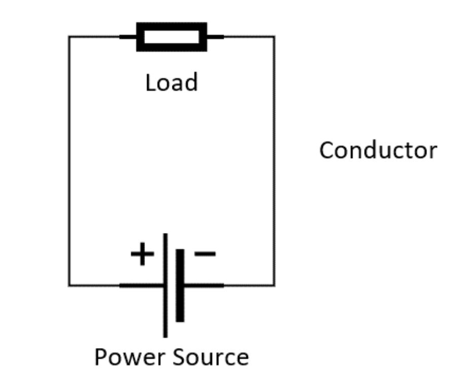
Charge Controller

What is the Task of a Charge Controller?

A charge controller is an electronic device designed to regulate the rate at which the electric current is added or drawn from a battery. It has three functions. The first one is to safely operate the battery's charging process to ensure that the battery will have a long lifespan.


Wiring the solar panel to the charge controller


During the charging process, the charge controller measures the state of charge (SOC) of the battery. Based on the measured value, the charge controller increases or decreases the electric current to comply with particular stages of charge in the battery.


The principal stages involved in the charging process for lead-acid that every charge controller should comply with are:


  • Bulk: high electric current charge increases the voltage of the cell.
  • Absorption: stabilizing voltage requires slowly reducing the charging current.
  • Float: the final process requires a very low charging current.

The following image shows a sample of the charging process in a lead-acid AGM battery using a charge controller.


Charging cycle of a VRLA battery

Source: Rolls Battery Manual


There are several battery types available on the charge controller to choose from. Every type of battery has a different charging profile. For example, lithium does not have absorption and float. Make sure the charge controller you buy is compatible with your battery.


The second important option of the charge controller is to efficiently and safely discharge the battery to supply energy to the connected loads.


During this discharging process, the charge controller must be able to prevent drainage of electric current beyond the designed depth of charge to protect the battery life. It must also detect overload and short-circuits and act to stop the flow of current if necessary. This is only applicable if your load is attached to the load terminals of the charge controller. As previously mentioned, it’s best not to use these terminals because they have a low power output. Some charge controllers don’t have load terminals anymore. We will talk more about connecting loads to the charge controller later in the book. If we do not use the load terminals on the charge controller, we need to use a low voltage disconnect to prevent irreversible damage to the battery. We talked about this device in the battery chapter ‘over-discharging’.


The third function of the charge controller is efficiently and safely extracting solar power from the PV modules and adjusting the power output of the solar array to the required voltage for the battery (generally 12V, 24V, or 48V). While connecting solar panels in series and parallel, the voltage of the string can reach voltages higher than the nominal value for the battery bank.


Another function is that the battery’s voltage is higher during the nighttime than the solar array, which could make the flow of energy go from the batteries to the panels. Therefore, an important duty of the charge controller is to block the discharge at night to avoid these reverse currents.


If the solar panels were to be connected to the battery directly without a charge controller, you would be overcharging the battery, which leads to damage and eventually destroying it. The charge controller frees the system designer from closely matching the PV voltage to the battery’s voltage and allows to set longer strings than what they could have been without the charge controller. Never connect a solar panel directly to a battery.

Different Charge Controllers

Charge controllers can be divided into two main groups according to the operation modes. These two main groups are PWM and MPPT charge controllers.

PWM

The Pulse-Width Modulated (PWM) charge controller was the first model that appeared in the market and is the most basic (and cheapest) type of controller that you can find.


The PWM charge controller acts like a switch that connects the output of the photovoltaic modules with the battery bank. Once the switch is closed, the voltage in the terminals of the charge controller will be the nominal voltage of the battery.


The charging process of the PWM model consists of closing the switch during the first stage of the process to the maximum possible current value as voltage gradually increases. When the voltage reaches the absorption voltage value, the current decreases slowly by disconnecting and reconnecting the switch multiple times.


This creates a pattern that has the shape of small pulses until the current drops to zero. The following image shows the charging process of a PWM charge controller.


Charging process of a PWM charge controller

Source: A.Luque y S.Hegedus.

“Handbook of Photovoltaic Science and Engineering”


The PWM charge controller always sets the output voltage close to the nominal voltage of the battery bank (generally a little higher to be able to charge it). Then, the regulator will provide the corresponding current in the I/V curve of the solar array.


The following graph shows an example of the output of a PWM regulator for a 12V battery. As can be seen, the PWM controller does not operate at the maximum power point (81 Watts).


PWM and MPPT charge controller curve comparison

Source: Victron Energy


When using a PWM charge controller, you must closely match the solar panel's voltage to the battery bank. There will be high losses if you do not closely match the voltage to the battery voltage. This means that when operating a PWM controller, you will likely have to wire the panels in Parallel, which increases wiring cost.


Here is an example of what happens when you connect a PWM charge controller without matching it to the battery voltage.


The voltage into the charge controller will be 20 Volts. The PWM charge controller cuts the voltage to 13 Volts to charge the battery, so you lose about 7 Volts because the PWM doesn’t track the MPP (maximum power point).

The power loss over the PWM charge controller will be 35%, resulting in a 65% efficiency. Therefore, it’s essential to match your solar panels to the voltage of your battery bank. PWM charge controllers are available in different voltages to match the battery at 12V, 24V or 48V.


Loss of energy when using a PWM charge controller

MPPT

The second type of charge controller is the maximum power point tracker (MPPT). This controller is a DC-DC converter (a device that takes a DC signal and transforms it into another DC signal with other parameters).


The operation mode of this type of controller consists of adjusting the voltage in the output terminals according to the voltage required to charge the battery bank.


At the same time, the controller tracks the changes in the solar array across the day in the I/V curve and locates the maximum power point of the curve every time. After locating this point, the controller determines the amount of electric current needed to provide the same amount of power as the MPP would provide, but at the battery's nominal voltage.

Instead of simply assigning the corresponding electric current in the I/V curve (like the PWM controller does), the MPPT model increases the electric current to reach the maximum power point.


In comparison to a PWM, which can have a 35% loss, an MPPT charge controller has a loss of 2 to 6%. In the following image, we can see that the MPPT controller increases the current at the output.


The efficiency of an MPPT charge controller


PWM or MPPT?

As has been previously explained, a PWM charge controller does not operate at the maximum power point of operation. This means that the power output obtained from a solar panel array when using a PWM model is much lower than the MPPT model.


In commercial-based or residential systems, the MPPT charge controller must always be the preferred choice since the extra amount of energy obtained from the I/V curve exceeds the additional cost of the MPPT model.


There is a particularly important factor to consider when selecting the charge controller. If the solar array has many solar panels in series, then the voltage is higher. As the voltage gets higher, the maximum power point (MPP) distances from the nominal voltage of the battery bank.


Keep in mind that the impact of six solar panels wired in series for a 12V battery bank is not the same as for a 24V battery bank. This is because the extra voltage difference will be higher in the 12V battery bank (and so will be power losses).


Therefore, if you have multiple solar panels wired in series, then the PWM charge controller would have much more losses than the MPPT model. In this case, it is recommended to choose the MPPT charge controller. Having more solar panels wired in series also reduces the amount of current, and therefore, reduces the cross-sectional area of the wires that would be needed, which translates into cost reductions.


There is no specific voltage at which you should consider switching from a PWM to an MPPT. Nevertheless, keep in mind that you need to have a higher voltage in order to charge the batteries. Therefore, if you have a battery bank at 12V, you will need to have at least 14V at the source (panels). PWM charge controllers are, most of the time, limited to an input voltage of around 12 or 24 Volts.


Also, keep in mind that voltage can reduce with temperature changes. Therefore, it is advisable to have a solar panel setup that provides between 17-19V (maximum power point voltage) for a 12V battery bank with a PWM controller. Adding more panels in series over this limit will simply increase losses.


The most common approach is to wire modules in series to reach string voltages between 54-58V. In the case of a 24V battery system, it is recommended to use a panel between 32-36V (Vmpp) or use two 18V panels wired in series to reach a similar voltage. For 48V battery banks, the situation changes a bit since it is unlikely that you use solar panels with 60V to be wired in parallel. And, for 48V systems, it is highly recommendable to use an MPPT charge controller.


Despite taking these measures, keep in mind that you will lose efficiency by using a PWM charge controller. Unfortunately, it is unavoidable due to the structure and functioning of the device.


Another factor to consider is shading. Under shading conditions, the MPPT charge controllers will have a much better performance than the PWM models because the MPPT models can track the array's maximum power point (which will become affected by the presence of shade). Therefore, if your solar panel installation is expected to have shading conditions, it’s better to choose an MPPT model.


Despite all of the advantages of MPPT charge controllers, they can be considerably more expensive than PWM models. Therefore, the decision comes down to a balance between costs and performance.


A PWM charge controller can become very handy for small loads or a trickle charger to reduce costs.


Because off-grid applications like a van, boat, or cabin have limited space to put solar panels, we need to extract as much energy as possible from the panels. The best way to do this is with an MPPT charge controller.


Selecting a Charge Controller

When choosing a charge controller, you must consider multiple factors. We will look at a datasheet from a widely used charge controller, the Rover series by Renogy.


Renogy Rover series charge controller datasheet

Voltage of the Battery Bank

One of the first things that should be considered when selecting a charge controller is to verify that the nominal output of the charge controller matches the battery. Typical applications will be 12 or 24 Volts.


If you intend to use a bigger nominal battery bank voltage, make sure the charge controller you select can set the voltage to that specific value. In this example, we can see that the maximum battery voltage is 32V. This is for a 24 Volt battery.

Rated Battery Current

This is the value that you will see displayed on the charge controller. It is one of the most important features when choosing your charge controller. This number indicates the amount of current that will go to the battery at the specified system voltage.


Let’s explain this with an example. We have two solar panels with the following specifications:


If we wire both panels in series, the voltage will double while the current stays the same. So we get 35 Volts and 5.8 Amps. Using the safety factor of , we need to choose a ()  10 Amp solar charge controller to charge the battery.


However, we do not charge our batteries at 35 Volts. The charge controller steps down the volts to a range of 12.9 Volts to charge the battery. This conversion increases the current (only with MPPT).


The combined power of both panels is 200 Watts. Let’s calculate the current at a charging voltage of 12.9 Volts.


You can see that the charging current to the batteries is higher than the previously calculated 7 Amps. The new charging current is 18.6 Amps, including a safety factor of 1.2. This means that you would need to get a 20 Amp charge controller.


Power conversion of an MPPT controller and 12V battery


Let’s repeat the calculation with a battery bank of 24 Volts.


As you can see, the charging current is reduced because we are charging at a higher battery bank voltage. When the charging voltage increases, the charging current will decrease. That’s why it’s cheaper to use a higher voltage battery bank. You will also save on wiring costs because you need thinner wires with lower currents.


Charging at a higher voltage will increase the charge controller’s efficiency because the charge controller doesn’t need to step down the voltage to 12 Volts. We would now need a 10 Amp charge controller instead of a 20 Amp charge controller.


Power conversion of an MPPT controller and 24V battery


Increasing the battery bank's voltage allows you to use a smaller charge controller because the charging current will be lower. As a result, the charge controller with a lower charge current will be cheaper.

Load Current

As mentioned before, we generally do not use the load terminals of the charge controller unless it’s a small load. It is best to use the battery terminals to power AC and DC loads combined with a low voltage disconnect.

Input Voltage

Another factor that must be considered is related to the estimated operating voltage ranges for the PV array.


As previously discussed, the solar panel voltage varies across the day, depending on the temperature. Moreover, it also changes depending on the number of solar panels connected in series. Therefore, when sizing a solar array, you need to estimate the number of solar panels that need to be connected in series. The more panels in series, the higher the voltage.


The charge controller that you selected will have both a maximum and a minimum input voltage from the solar array that it can handle. Whenever choosing the charge controller, you need to make sure that the input voltage does not go over that range.


You must consider the effect of temperature on the cell voltage, as explained in the solar panel section. In other words, the maximum input voltage that the charge controller can accept should be associated with the voltage of the string under minimum temperature conditions. Meanwhile, the minimum input voltage that the charge controller should accept is related to the voltage of the string under the maximum temperature conditions. Most MPPT charge controllers have a maximum input voltage of 100 Volts DC.

Power

Another factor is power. The charge controller is capable of handling a specific amount of power input from the solar panel(s).


As you already know, power is the product of voltage and current. The power of a solar string or array is the same in every configuration (series or parallel). The voltage refers to the nominal battery voltage.


We can see that a higher battery voltage allows a larger solar panel input. This is because the components of a charge controller are selected according to current. Raising the battery voltage by a factor of 2 (from 12V to 24V) will decrease the current by a factor of 2. That’s why we can have a higher power input when the battery voltage is higher.


Maximum input power is related to battery voltage

Efficiency

Efficiency is important to consider. When deciding between two charge controllers, the model with higher efficiency is preferable. MPPT controllers are the best option.


Since charge controllers are electronic devices intended to act as intermediaries between the charging source and the load, then charge controllers should transfer as much energy as possible. Therefore, efficiency should always be located above 94%. Efficiency will be higher (98%) when you choose a 24V battery system compared to a 12V battery system. This means that a charge controller will be more efficient if you match the solar voltage to the battery voltage because it needs less voltage transformation. More transformation means more heat generation, and the charge controller will be less efficient.

Operating Temperature Range

Each charge controller will also have a permissible operating temperature range. Keep in mind that the cabin or cabinet where you locate the regulator will have the allowable temperature or humidity limit values stated by the charge controller manufacturer. Also, take into account the enclosure protection rating, typically established according to the IP ratings. Do not put the device in an area that can become wet.


PWM charge controllers operate better with estimated solar cell temperature ranges between 113°F (45°C) and 167°F (75°C).


MPPT charge controllers outperform PWM models under all cell temperature conditions, but especially when they are either below 113°F (45°C) or higher than 167°F (75°C).

Temperature Compensation

As explained before in the battery section, temperature changes can severely affect batteries. The battery capacity can drastically reduce as it approaches 32°F (0°C) and even more if it lowers. Combining this temperature effect with high load demands can lead to a severely reduced state of charge (SOC) in your battery.


Voltage charging setpoints are usually established for charge controllers assuming 77°F (25°C), which is the standard for batteries. However, as the temperature increases, the charging voltage lowers. If the temperature decreases, the charging voltage rises. To avoid overcharged (which can lead to gas expulsion) or undercharged (leading to sulfation in lead-acid) batteries, the charge controller must integrate temperature compensation.


Chargers can either have fixed temperature compensation voltage (e.g., 5mV/°C/cell) or an adjustable setpoint. Having an adjustable setpoint is advantageous since battery manufacturers can recommend different temperature compensation values.


For instance, Rolls and Victron Energy Batteries recommend 4mV/°C/cell while Crown and Deka recommend 3mV/°C/cell.


Each charge controller also has a specific temperature compensation range, generally between 32-122°F (0-50°C). If ambient temperature goes beyond the limits, then compensation is set at the nearest value.


The temperature compensation that the charge controller makes consists of using the nominal system voltage, the nominal charge voltage at 77°F (25°C), the temperature compensation rate, and the battery temperature.


As a reference example, let´s assume a 24V system, with a charge voltage of 28.6V, along with a temperature compensation rate of -5mV/°C/cell and a battery temperature of 113°F (45°C).


Since the system is 24V lead-acid, it has 12 battery cells (2V per cell). Then,


The new charging voltage for that battery bank would be 27.4V instead of 28.6V. As you can see, the voltage is reduced.


There are two types of charge controllers in this aspect. Some models already integrate an internal temperature sensor and can perform this function directly. These models are quite helpful when the battery bank and the charge controllers are located inside the same enclosure and have similar temperatures.


There may be occasions in which the battery and the charge controller are located in different enclosures. In these cases, it is appropriate to choose a remote temperature sensor. Remote temperature sensors consist of a wire with a terminal pin to be connected to the charge controller and a sensitive probe to be used for testing and measuring temperature. This is also recommended when the temperature changes across the year step over 5°C.


Most of the higher-end MPPT charge controllers have a port where you can add a temperature sensor. The charge controller will use the temperature and calculate the ideal charging voltage according to your battery type. Then, you put the sensor in the same compartment as your batteries. You can use tape to stick the sensor to the side of your batteries for the most accurate compensation.


If you are using lithium batteries, you should be using a temperature sensor which is located on the BMS. If you charge the battery when it’s freezing, it’s permanently damaged. The temperature sensor can detect this and disable the charging of the battery.


Image result for charge controller temperature sensor

Temperature compensation sensor


Temperature compensation on the Renogy charge controller

Connecting the Charge Controller

The procedure of wiring a charge controller into the system is very simple.


Charge controllers generally have two output terminal sets: one for the battery and the other for the load. Also, charge controllers will have a single input terminal set connected to the solar panels.


When wiring the charge controller, you must first connect the batteries to their corresponding output terminals. Then, you connect the loads to the load outputs. Then wire the solar panels to the charge controller.


Connection sequence for the charge controller


The load terminal on the charge controller can only supply a limited amount of current to loads. Therefore, we attach small DC loads to the charge controller, and we connect the inverter straight to the battery terminals. Always keep in mind the maximum load current of the charge controller listed on the datasheet. If the total DC current of your appliances is higher than the rated output current of the charge controller, then connect the DC fuse box to the battery.


The load terminal on the charge controller is not capable of providing surge power. That’s why it’s recommended to use the battery terminals for inverters. See the following image for reference.


Wiring the charge controller


Keep in mind that the charge controller input and output will have a maximum gauge size connected to the terminals. This will depend on the electrical current output of the charge controller.


If you want to do maintenance and disconnect the PV system, always remember to disconnect the DC switch between the charge controller and the solar panels. Once this is done, proceed to remove the load connections before removing the battery's connections from the charge controller.


In other words, solar panels are the last ones to connect and the first ones to disconnect.


Disconnecting sequence


Always check the polarity of the wires with a multimeter before connecting it to your charge controller. Ensure to check the solar power input voltage, so it’s not higher than the allowable max input voltage.

Multiple Charge Controllers

There are many reasons why you would want multiple charge controllers. These are:


  • Adding more solar panels to your system.
  • Adding a panel with a different specification than the one you already got.
  • Separate panels from each other because they receive shade at different times of the day. For example, on a boat or multiple sides of the roof.

Adding more charge controllers to the same battery isn’t a problem. The charge controllers detect the battery's internal resistance instead of the voltage to determine the charging current. If the internal resistance is low, the battery is empty. If the internal resistance is high, the battery is full. Both (or more) charge controllers will charge their full current into the battery bank.


You have to make sure that the battery can handle the current of both charge controllers combined. This is going to be easier with lithium because it can tolerate a higher charging current.


If you have lead-acid batteries, you must be careful not to charge lead-acid too quickly with too many amps. Read the manual on the max recommended charging current or C-rate.


You also need to disable the equalizing function on the other charge controllers and only have it enabled on one controller (the master). Otherwise, the battery will get equalized by every charge controller randomly.


The charge controllers do not need to be able to communicate with each other. Some charge controllers can connect through a cable or Bluetooth. This is a nice feature, but it is unnecessary to safely operate multiple charge controllers for one battery bank.


The following image shows you how to wire multiple charge controllers to one battery bank. It is recommended to make the wires that go from the charge controller to the battery the same length. This is to make the resistance in the wires the same so that they charge equally.


Multiple charge controllers for one battery bank


You can program the second charge controller to come on a bit later than the first charge controller. You do this by increasing the bulk charging voltage values. The same goes for the float voltage values.


Let's take a look at the last component of the solar power system. The inverter.

Inverters

What is the Task of an Inverter?

Finally, the PV system's last but still important component is the inverter.


The most important task of the inverter is to convert the DC signal in the batteries into the AC signal consumed by most loads. As it was explained at the beginning of this book, there is an important difference between DC and AC signals.


Since solar panels generate DC, and most household loads require AC signals, the inverter acts as a DC-AC converter that can or cannot synchronize (depending on the model) with the signal obtained from the power grid.


However, there are different types of inverters, and depending on the type, they may have alternative functions. Large inverters of 1000 Watts or more have large capacitors to create the AC signal. The capacitors will charge immediately when you connect the inverter. This will create sparks. Sparks are not desired because they can damage the electronics and terminals.


That’s why it’s best to use a resistor in series to limit the current flow into the inverter on the initial connection. These resistors are called pre-charge resistors. They are anywhere from 5 ohms to 30 ohms. Connect the positive lead to the inverter first and then use the pre-charge resistor to touch the negative wire from the batteries with the negative terminal of the inverter for a few seconds. This will make a connection with a low current without creating sparks.


25-Watt, 30 Ohm resistor

Types of Inverters

Off-grid

For applications in RVs, cabins, and boats, the most common type of inverter that we will be looking at is the battery-based inverter (also applicable for inverter/chargers) suitable for stand-alone setups.


This type of inverter works independently from the power grid and can be used with lead-acid or lithium batteries. It will be connected directly to the batteries and will have a DC input value at the battery's nominal voltage (generally 12V, 24V, or 48V). This type of inverter will create its own AC signal and is capable of providing overload protection.


Always remember that the AC loads must be connected to the AC side of the inverter, which is in the output terminal. AC loads must never be connected to the charge controller because the charge controller (no matter what type) will always work in DC (except all-in-one units). The only loads that you can connect to the charge controller are DC, like small LED lights, smartphones, and other small electronic loads. The wiring for this type of inverter can be found in the following image.


Off-grid inverter setup

Grid-Tied

The most common type of inverter available is the grid-tied model. This inverter is used when the power grid is available for connection and when no battery will be used.


This applies mainly to residential, commercial, and utility-scale applications. This type of inverter needs a signal from the power grid to get synchronized since it cannot create its own AC signal. Therefore, when the power grid goes down, the inverter shuts down. This is to protect people working on fixing the electrical lines from being electrocuted.


The input of this inverter is the solar panel. It can perform the maximum power point tracking, while the output is an AC source signal at 50 or 60Hz. The output signal of the inverter will have a slightly higher voltage than the grid. This is to make the electricity flow from the inverter to your home appliances instead of power from the grid. If the voltage level in the grid rises, the inverter will track the change and increase its output voltage level.


If you have an RV, off-grid cabin, or boat, a grid-tied inverter will not work for you. If you are using grid-tied, you need permission from your electrical company to feed electricity back into the grid. The following image shows a schematic of the connection of a grid-tied inverter.


Grid-tied inverter

Hybrid-Inverter (all in one)

The hybrid inverter is the most advanced and complex inverter available in the market. This device integrates the benefits of an MPPT charge controller, inverter, and battery charger into a single product. An automatic transfer switch could also be included.


The hybrid-inverter can receive the signal from the solar panels and track the maximum power point to extract solar energy, just like an MPPT charge controller.


It can use this energy to store it into a battery, combining the advantages of available power from the grid with energy storage. Some models can synchronize with the grid when it is available. They can also generate their own AC signal when a blackout occurs.


Hybrid-inverter schematic


One of the advantages of hybrid inverters is that they can charge the batteries without the need for a charge controller, and they can use both the wall outlet to charge your batteries as well as solar power.


Technically, you could buy the inverter only for that purpose. However, you would be underestimating its potential as you would still constantly depend on shore power to charge the batteries and power your loads. By installing solar panels, you would be able to move with the RV and travel for days without getting worried about the availability of shore power.


If you live in an RV, using a hybrid inverter alone might as well suit your needs.


The hybrid inverter will use the battery bank to make an AC signal if there is a blackout or if you are on the road. If it detects that there is power being produced by your solar panels or onshore power (at a campground), it will use that power and charge the batteries.


The disadvantage of a hybrid inverter is that they tend to consume quite some power in standby mode. If you are only using DC, the inverter will be idling, constantly consuming power. It might not be much, but you should consider it if you have a small system. Some hybrid inverters have an option to turn off the inverter with a separate switch.


The hybrid inverter can be used for the following case. You are plugged in and draw 20 amps from shore power, the solar panels produce 20 amps, and your AC unit draws 40 amps. Now you can run your AC without drawing power from the battery.

Be careful about cheap hybrid inverters. If the price difference is significant compared to others, they might use a PWM charge controller. Always check the specifications of the product carefully.


Some popular brands for hybrid or all-in-one inverters are MPP Solar (‘maximum_solar’ on eBay), Victron, and Growatt. Hybrid inverters can make a lot of noise because of their fans. Consider this when buying your hybrid inverter. Another point to watch out for is if they include a grounding relay. We will talk about this at the end of the chapter.

Inverter/Charger

This might be the best solution if you still want to use a separate charge controller. This inverter not only converts DC voltage from the battery to AC loads but is also capable of charging the battery itself. It’s a cost-efficient solution if you want to charge your batteries with shore power while on the road.


Most of the time, these come with a temperature sensor to adjust the charging of the battery according to the battery's temperature. Unlike the hybrid-inverter, the inverter/charger does not include the solar charge controller. How to wire the inverter/charger can be seen in the following diagram:
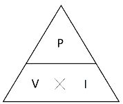
 

Wiring diagram for an inverter charger


Apart from using shore power, you can also use a portable generator to connect to the AC input of the inverter/charger to charge the batteries.


Wiring inverter charger with shore power and a generator

Inverters Output Signal

Besides their configuration type, inverters can also be classified by the shape of the signal wave at their output.

Square Wave

These are considered the oldest technology available for inverters. Their working mechanism tries to resemble the periodic shape of an AC signal by flipping the voltage directly from negative to positive and back again.


Unlike a typical AC signal, there is no pause through zero between the negative and positive voltages. Due to this alternating pattern, they resemble the shape of a square.


Today, square wave inverters are not considered for many applications because most loads would heat up when using them. The reason is that electronics require smoother signals free of harmonics (noise components).


Square wave inverters have a much higher noise level than a sine wave inverter, which creates a real disturbance. Square wave inverters can be much more affordable than their sine wave counterparts despite these flaws. This is because the square wave is an older, less complex type of inverter.


The only applications where purchasing a square wave inverter might be suitable would be to power lights and fans or small motors.


Different Types of Inverters

Square sine wave

Modified Sine Wave

The modified sine wave inverter is another version of the inverter that came after the square wave type that had better performance and was more similar to an actual AC sine wave signal.


Unlike the square wave type, the modified sine wave adjusted the ups and downs of the output signal to match the shape of an actual AC sine wave signal as closely as possible.


Different Types of Inverters

Modified sine wave


Despite having better performance than the square shape type inverter, the modified square wave inverter will still have a noticeable harmonic distortion that will not allow it to run sensitive electronics such as laptops. Besides, you are likely to hear a “buzz” when operating it. Modified sine wave inverters are cheaper than pure sine wave inverters.

Pure Sine Wave

The most efficient, technological, and undoubtedly ideal option for any load is the pure sine wave inverter. The signal of this inverter resembles exactly the one that could be measured in the power outlet of your house, meaning a perfect sinewave.


Sensitive electronics need the cleanest signal available to work without any risk of damage. Despite that, they will be more expensive. They will not be as noisy as the square wave model, they will not heat up your appliances, and they will work better in cases where there is constant use across the day.


Different Types of Inverters

Pure sign wave

Utility Interactive for on-grid Connections

Inverters connected to the grid (grid-tied or hybrid inverters) have additional features that off-grid-based models do not need. Due to their connection with the grid, inverters can act under different interactive modes of operation depending on the conditions of the power grid.


The first type of connection available is the simple grid-tied mode, which exports all the energy generated by the solar panels back to the grid. There are multiple compensation schemes available out there, depending on your location.

For U.S.-based cases, you will find schemes such as Net Metering and Feed-in tariffs that will compensate you for every kWh injected back to the grid.


Nowadays, inverters are capable of more. Some inverters known as smart inverters can interact with the power utility operator to guarantee the safest operation of the power grid.


Using high-tech communication systems, a network operator is capable of shutting down all inverters within a perimeter in case the solar power injection to the grid exceeds the limits for the stability of the system.


Network operators can also curtail or adjust the power factor of smart inverters to reduce or increase solar power injection into the grid. Some networks, such as the Hawaiian power grid, already operate under these mechanisms. Hybrid inverters have other functionalities as well. Some of them are:


  • Backup: Isolating operation from the grid when there is a blackout.
  • Grid Zero: Does not allow selling energy to the utility. The inverter tries to avoid consuming power from the grid, only using the renewable energy source and the batteries.
  • UPS: Intended to increase the response speed to support specific loads (important for data banks).
  • Mini-Grid: Operates as an off-grid system, using the utility grid as a backup.
  • Time-of-Use: Inverter is set to take advantage of low-cost electricity rate periods to consume power from the grid and use high-cost electricity rate periods to sell power back.

Efficiency

The efficiency of an inverter as any other conversion device is essential to ensure the proper use of the generated solar power.


Efficiency is referred to as the amount of power of the DC signal that enters the inverter, compared with the amount of power in the AC signal that comes out of the device. Inverters should generally have efficiency values above 93% to reduce energy losses. However, the latest inverters will have efficiency values above 97%.

Automatic Load Shedding

The term load shedding is a technical term referred to as reducing the amount of load (power) connected to a generator, energy source, or electrical system. This is done to ensure that the electrical system can provide power to the most important (critical) loads uninterruptedly.


In a solar power system that is off-grid based, it is important to consider during low solar radiation days that the availability of power may be lower than expected. That’s when an automatic load shedding control mechanism or device becomes handy.


Some inverters already integrate this feature (like the SMA Sunny Island inverter). However, you may also find separate devices that can perform this task. This will allow you to prioritize the loads you want to keep running in increased load demands or low electricity generation.

Low Voltage Disconnect

Some inverters have a low voltage disconnect feature built-in. When the batteries go below a specific voltage, the inverter automatically turns off the loads. This feature can be helpful if you do not use a separate low voltage disconnect.

If you do not know the existence of this feature, it might be frustrating to see that your inverter is shutting down when the battery is almost depleted. It is best to let your low voltage disconnect trip first and then use the inverter low voltage disconnect as a backup. When buying an inverter with this feature, make sure it’s suited for the battery type you will use. Different battery types have different disconnect voltages.

Peak Power

Peak power is the maximum power that the inverter will provide during a short time. Surge power follows a similar concept, although under a shorter time frame. It is important to mention that this does not apply as a reference for the power capacity of the inverter when sizing the system. The peak or surge power can be used as a reference for those loads that require extra power during the starting process, such as motors.


Depending on the inverter model and brand, you will find some products that offer different peak power capacities under different time frames. For instance, a 2,000W inverter may provide a peak power of 2,500W over 30 minutes (just in case the load demand slightly increases). It may even provide a surge power of 4,500W for 5 seconds (only suitable for starting loads with motors like a fridge or A/C unit).

Power Consumption

Power consumption is another factor to consider since every inverter will demand a small power consumption to keep electronics working, even when there is no load connected.


Despite that power consumption tends to be small, selecting the inverter with the lowest power consumption is always preferable. It is best to turn off the inverter when not using it. Look for an inverter with a switch or remote switch.

Parallel Inverters

It is possible to wire two or more inverters in parallel to increase the power output. However, these inverters need to sync with each other, so their sine waves are at the same degrees. One 1,000-watt inverter wired in parallel with another 1,000-watt inverter will deliver a total of 2,000 watts.


Most hybrid inverters can communicate with each other through an ethernet cable. Always check that your inverter can perform parallel functioning. Most stand-alone inverters cannot.

Charging from Alternator

Solar energy is entirely dependent on the weather conditions of your location. You may find yourself in a situation where multiple rainy days can keep your solar panels from completely charging your batteries. Or over time, you can also be consuming more power than what your system was designed for.

Either one of them, having an alternative energy source to charge your batteries, is always preferable.


There is an additional available energy source in vehicles that can be used to charge your batteries. We are talking about the car alternator. Just as the vehicle moves and charges your starting battery, it can also power an auxiliary battery. There are two ways of doing this.

Battery Isolator Charger

The first option is to use an isolator charger.


The purpose of an isolator charger is to connect your vehicle’s alternator to the solar battery and charge it when the car is running. However, when the vehicle stops, it will drain your starting battery. Therefore, the isolator charger ensures that you isolate the starting battery from the solar battery when the engine is not running. This is the lowest cost option.


Direct charging from the alternator can be damaging to the alternator and battery. This is because there is no current limitation or regulation for the charging process. Therefore, it is not recommended to use an isolator charger.


A car alternator is not made to charge deeply discharged batteries. The current demand from the alternator to the solar battery will be too high for the alternator. This makes the alternator provide more amps than it can safely handle and will lead to overheating and eventually the destruction of your car’s alternator. This is especially true with lithium batteries because they have low internal resistance.

Battery-to-Battery Charger (B2B)

The second option is using a battery-to-battery charger or B2B device, also known as DC-to-DC battery chargers.


This device is located between the starting battery and the solar battery. Its purpose is to take the car starter battery and boost or reduce it to provide a stable voltage under a multi-stage charging profile. This ensures that the solar batteries are safely charged while keeping the main starter battery full.


Renogy offers a B2B device that connects to your car’s ignition. It only runs when the car engine is running. You can select several options for battery type and battery voltage using the switches on the side.

Battery-to-Battery charger from Renogy


The difference between a B2B and an isolator charger is that the B2B can perform a multi-stage charging scheme (the most optimal charging method). It should also come with a lithium charging profile.


Wiring diagram for a B2B charger


When selecting a B2B charger, you must look at the maximum output and input currents and the permissible voltage values. A 10 Amp or 20 Amp B2B charger will suffice in most cases.

Charge from Generator

Although less common in solar power applications, another option is to couple an inverter/charger with a traditional gas or gasoline generator. The backup generator can be connected to the AC input.


Keep in mind that this modality is available for hybrid inverters (through their AC input) and some inverter/chargers that integrate an AC input for backup support through a diesel generator. Not all models have this feature available, so you need to look in the datasheet or installation manual to see if there is an AC input terminal for such a device.

One sample inverter/charger that has this feature available is the Outback Power FXR series with a 48VDC input that needs to be provided by a charge controller of the brand. Make sure that the inverter charger is compatible with your type of battery.


Hybrid inverter with a backup generator


Inverter/charger setup with shore power or generator

Grounding

We ground electrical systems to reduce the effects of static electricity, surges, over-voltage, and many more.


Grounding, earth, or chassis have the same meaning. Its purpose is to reduce over-voltage and improve the safety of electrical systems in combination with a GFI.


Lightning

In the case of lightning, you need to connect all metal parts to the grounding busbar. If a metal pipe in a building is not grounded, and lightning strikes that pipe, it cannot find a way to go to earth. In this case, the electrons will try to find a way to another metal object. Arcing can happen, which can result in a fire. Or even worse, death to the person standing next to it.


This kind of grounding is called equipment grounding. Its purpose is to give electrons a path to ground. Equipment grounding is not to protect your system from lightning. Whenever a lightning strike hits your solar panels, expect damage. Lighting protection is a whole other subject, and is not the same as equipment grounding.


Electrocution

To be electrocuted, the current has to go through your body. There are different systems on how to protect yourself from being electrocuted. One misconception is that a circuit breaker will protect you from electrocution. This is not the case.


Another misunderstanding is that electricity takes the path of least resistance. This is not true either. Electricity will flow wherever it can in parallel paths. Let me explain this with an example.


Diagram  Description automatically generated

Current flowing through a person


In this image, a person touches a live wire. The AC source is 120 volts alternating current. We know that in a parallel circuit, the volts are the same. The light will receive 120Volts, and the person touching the live wire will also receive 120Volts. In dry conditions, a person has a resistance of 1000 ohms from hand to feet. We apply ohm's law to figure out how much current will pass through this person's body.


This will not end well for the person touching the live wire. The current will travel through the body and return to the source. Here are several current ratings and their consequences to the human body:


  • 0.3mA: Sensation of touching a live wire.
  • 0.7mA: Your let go threshold.
  • 10mA: Max amount of current you can still let go of.
  • 50mA: Fibrillation of the heart, which is fatal.

We want to protect ourselves from these deadly situations. That is why we are going to incorporate a GFI. But first, we will talk about the different energy systems to make sense of why we should use a GFI.


IT and TT Systems


There are a few types of electrical systems. In this book, we will describe two networks that are the most common for off-grid (the others are not discussed in this book).


  • IT: unearthed systems (Isolé-Terre or isolated earth)
  • TT: earthed systems (Terre-Terre or earth to earth)

IT systems: The earth is not connected at the source. There is no connection between the negative and the earthing wire. Therefore, the energy cannot flow back to the source.


We can see from the following diagram that the person who is touching one phase is safe from electrocution. This is because the path to the source is not completed (there is no grounding at the source). It is the same as birds sitting on a high voltage exposed electric wire.


Now, if the person touches two phases, the circuit is completed. Current will flow through the person's hearth, and the consequence will be fatal.


Diagram  Description automatically generated

Consequences of touching a wire in IT system


This system is easy to install in off-grid applications. However, this is not the recommended system.


TT systems: The earth is connected to the negative wire. In a mobile situation, this is the negative terminal of a battery.


We can make a grounding connection at the source. You can do this by installing a ground rod. In mobile applications, you use the battery negative terminal.


If a person touches one of the live wires, the connection to the source will be completed. The current travels through the person to ground and back to the source. This is shown in the following image. The person can die because the circuit is completed through the body. This is not what we want because it is more dangerous than the IT system (because the current can flow back to earth).


Therefore, we include a GFI (ground fault interrupter). This device is used to detect any current leakage and will break the circuit as soon as it detects this leakage. The device compares the current going into the circuit (+) and returning (-). These two must be in balance all the time. If the current goes back through the earth (a fault occurs), the GFI will detect this and break the circuit. This happens very fast in less than one-tenth of a second. It needs to act quickly so your body doesn't get electrocuted.


Diagram  Description automatically generated

Consequences of touching a wire in a TT system


A GFI has many different names. It is known as the following: residual current device, earth leakage device, ground fault circuit interrupter, residual current circuit breaker, and residual current device. All these names refer to the same device.


In your home, you might have noticed that the GFI breaks the circuit unintentionally. This is because there is a current leakage to the earth. It can be a fridge where the compressor is not working as intended, and the whole house is shut down. It could also be a pump in your backyard where the GFI shuts off because the pump has a small current leak to the earth. This is all very good in household applications because you know something is wrong.

However, in an IT system, this won't work. Therefore, IT systems are used in industrial applications where one fault may not interrupt the current flow to keep machines working. The TT system is recommended for residential or off-grid purposes.


A GFI works with AC, so it needs to be placed right after your inverter to protect you on the AC side of the system. You can only have one neutral-to-earth connection (this is at your battery negative terminal).


All metal parts should be connected to the main ground terminal for off-grid mobile applications like a van or boat. For example, the outer hull of a boat or the metal framework from a van. When connecting to the framework, it's better to connect to the structural frame itself and not the thin side panels. Remove the paint with sandpaper, drill a hole and connect a wire to your grounding busbar. From the grounding busbar, you are going to add a wire and connect it to the main negative on the battery bank.


Diagram  Description automatically generated


The earth wire (Pe) should have the same diameter as the current-carrying wire associated with it. If the cable from the battery to the inverter is 4AWG, then the wire from the battery to the Pe busbar should be 4AWG as well. Companies have different guidelines on this matter. Refer to the manual of the charge controller and inverter for further guidance.


Inverter/charger or hybrid inverter

This system is safe with an off grid-connection. However, introducing an external charger like an inverter/charger or hybrid inverter brings an additional earth into the system. The following diagram shows you what happens.


Diagram  Description automatically generated


We can have two possible scenarios:


  • The inverter is taking power from the battery.
  • The charger is taking power from the grid or generator.

In a TT system, the earth has to be connected to ground at the source for the GFI to work correctly. In the two possible scenario's there are two sources of power: the battery and the grid. That is why there needs to be a ground relay inside the inverter/charger or hybrid inverter.


Once you connect the grid or a generator to your system, the ground will switch from your battery to the ground of the grid or generator. This device is called a ground relay. When you connect your system to the grid or a generator, it is crucial that your inverter/charger or hybrid inverter has a ground relay. Otherwise, your GFI won't work correctly.


In the following schematic, you can see the simplified working of a ground relay. When the grid is connected, contact 1 will be closed, and 2 will be open. This action enables the ground from the grid to be used while the ground from the battery is disabled.


When the grid is disconnected, contact 1 will be open, and contact 2 will be closed. Now the ground will be the negative battery terminal.


Diagram  Description automatically generated

DIY Solar Power Setup

The procedure for building a solar power system is straightforward and can be done by following these steps:


1.      Calculations and schematic

Before you order components or even consider making a solar system, you need to do the calculations first. Refer to the chapter ‘sizing your solar system’ for more information.


Drawing out your solar system will make it easy for you to assemble the components later. It will also give you an estimation of the space and components you will need.


2.      Ordering and preparing components

After you have done the load analysis, it’s time to order your components. Make sure you have read all the chapters in this book before buying your components to avoid unnecessary setbacks.


Remove the components from their boxes and put them roughly where you want them. Using a wooden backboard to mount the components can make it easier to install. Make sure to put them as close together as possible to reduce wire losses and save on wire cost (especially with thick wire). Leave some space for airflow. Make sure the connections are accessible for future upgrades or maintenance.


3.      Layout

Look for a space to place your batteries. Keep in mind to respect the limits and parameters stated in the National Electrical Code section of the book. Make sure the batteries are placed at room temperature if you have the option.

Place the inverter and the charge controller in an ideal position that is close to the battery bank. This reduces the voltage drop and allows an easier installation.


4.      Wiring the batteries

Remember to review the section related to series and parallel connections in the battery section of this book before wiring your batteries.


Choose your wire gauge wisely to handle the current flow from your charge controller to the batteries. Check the manual of the charge controller for the recommended wire thickness.


Add an inline fuse as close to the positive terminal as possible. Add a battery bank disconnect switch (high current low DC voltage switch).

Two batteries in parallel with fuse and switch


If you choose to use a shunt, now is the time to wire it in. The negative terminal of the shunt will act as the main negative battery terminal.


Shunt at the negative battery terminal


5.      Wire the battery to the charge controller.

Wiring the batteries to the charge controller


Once wired, the display of the charge controller will light up. Select the battery type you are using. Follow the directions in the manufacturer’s manual on how to do this.


6.      Install the inverter

You have two choices when installing the inverter:


  • Wiring directly to the battery terminals.
  • Wiring from a busbar.


Wiring from the battery terminals:


This option is easier than wiring from the busbar because you need fewer fuses. The downside to this setup is that it is harder to expand your setup later. Keep in mind that the maximum number of connectors on a terminal is three.


Wiring the inverter to the batteries


Fuse 2 needs to be able to handle the current that the inverter draws. If the inverter is rated for 1,000Watts, you need to know the amount of current that flows through the wire. For a 12 Volt system, this is:


There will flow a maximum of 83.3 Amps through the wire if the inverter uses 1,000 Watts of power. Select the wire diameter and choose the correct fuse for the wire diameter. If you do not want to wire directly from the batteries, you should install a busbar. The following image shows how to wire from the busbar.


Wiring the inverter from a busbar


In this case, the size of fuses 2 and 3 will be the same. If there are no other loads attached, it’s enough to use only fuse 2. However, if you are going to expand your system with a DC fuse box, the size of fuses 2 and 3 will not be the same.


If you choose an inverter/charger, install the AC input plug to accept shore power or power from a generator.

Installation of inverter/charger


7.      DC fuse box

You can connect the DC fuse box using the load terminals of the charge controller.

Connecting the DC fuse box


However, if the output terminals only supply 20 Amps, you will be limited to .


This can be a problem, especially if you have a lot of DC loads. Therefore, it is recommended to connect the DC fuse box to the previously installed busbar or the battery terminals.


Connecting the DC fuse box to the busbar


In this case, fuses 2 and 3 won’t be the same. You must calculate the maximum AC and DC loads using your load estimation and select the correct fuse for each. Add up fuses 3 and 4 to know the value of fuse 2. Select your wire according to the maximum amount of current that goes through the wire.


8.      Install the solar panels

Refer to the chapter about mounting your solar panels. Plan your solar panels so that the wire to the charge controller is as short as possible to limit voltage drop. Connect your solar panels with steel wire if you put them on a roof of a vehicle. If one comes loose, it won’t fly off.


9.      Wire the modules

Read chapter ‘series and parallel connection’ to understand how to wire the modules for your intended purposes.


Connecting three panels in series


In this example, the main positive of the panel is fused. The fuse size is indicated on the back of the solar panel. The solar string can be disconnected using the solar isolator switch if maintenance is required. Try to place the switch in a location where you can easily get to, preferably close to the charge controller.

 

The cable entry plate is a device that allows you to safely connect the output of the solar panels from the outside to the inside of the vehicle. Make sure to use enough sealant to protect your roof from leaking water during rain.


10.  Install the B2B charger

If you would like to charge the solar battery using the car battery, install the battery to battery charger. Refer to the wiring scheme given in the ‘B2B charger’ chapter.


11.  Testing

Congratulations, you have completed the solar system installation. Now you must run some tests. Testing includes:


  • Checking for loose wires.
  • Checking for sharp edges that can cut your cables.
  • Monitoring the temperature of components.
  • Monitoring the temperature of the wires.
  • Checking the battery voltage when fully charged.
  • Testing loads.
  • Check your wire connections at least once a year.

Solar System Examples

In this chapter, we will present some examples and explain the reasoning for wire thickness and fuses. This will be helpful to look back to when making your system.


Here are the systems we will discuss:


  • 12V 500W inverter with 400W of solar
  • 24V 1kW inverter with 800W of solar
  • 48V 3kW inverter with 3kW of solar
  • 48V 5kW inverter with 9kW of solar


Note about cable sizing: the cables in these systems are copper and are calculated with an insulation temperature of 75°C or 167°F. Do not use cables that are lower than this temperature if you plan to copy these systems.


The blueprints of these systems will be available on the website, https://cleversolarpower.com/offgridsolarbook where you can view them in color and a larger size.

12V 500W inverter with 400W of solar

Diagram, schematic  Description automatically generated


This system is suited for small loads no larger than 500W AC and 250W DC. Both loads can be active at the same time. The battery gets charged with two solar panels for a total of 400W. Both 200W panels will be wired in series to the charge controller (Epever Tracer 4210AN), where it charges the battery at 33A.


Next, I'm going to explain the wire sizes and fuses.


F1: This wire goes from the solar panels to the charge controller. The Isc (current short circuit) of this 200W panel is 10.2A, and the Voc (volt open circuit) is 24.3V. The maximum current through this wire will be:



Therefore we will use a fuse of 20A. 20A is the fuse size that rich solar (the solar panels manufacturer) recommends. This fuse will be an inline MC-4 fuse.


Next, we will calculate the wire itself. We assume the charge controller's wire length is 20ft or 6 meters. If we plug this in a voltage drop calculator:

(https://cleversolarpower.com/voltagedropcalculator)

At 50VDC, we become 12AWG or 4mm² with a voltage drop of 2%.


A solar disconnect switch is situated between the solar panels and the charge controller. This is used to isolate the solar panels from the charge controller if maintenance needs to be done.

 

F2: The following wire goes from the charge controller to the busbar. The maximum current that can go through this wire is:


A safety factor of 1.25 needs to be applied:


This is over the charge controllers max output. We will have a small loss when the conditions are better than STC. This will be very limited, so we will use the 40A charge controller. The controller will not be damaged, only limited to 40A.

 

The charge controller manual says that we need to size our wire 1.25 times over the max output current. This is the temperature correction factor.


A wire suited for 50A is a 6AWG or 16mm². Since the maximum current from the solar panels will be 41.6A, we will use a 50A fuse.


F3: This wire goes from the busbar to the inverter. The inverter has a power rating of 500W. That means we have a current of:


We must multiply this by a safety factor of 1.25, so the new current will be 52A. A wire which can carry 52A is 6AWG or 16mm². We will use a 60A fuse for this wire.


F4: This wire goes from the busbar to the DC fuse box. Let's assume the fuse box will have a max load of 250W. That means this wire needs to carry:


We multiply with a safety factor of 1.25 and become 26A. A wire suited for this current is 10AWG or 6mm². Since we have a max load of 20.8A, the closest fuse is 30A.


F5: This wire goes from the busbar to the battery. The maximum current this wire will carry is the sum of the inverter and the DC fuse box. This is


After the safety factor of 1.25, we become 78A. A wire that can carry 78A is 4AWG or 25mm². We will fuse this wire with a 90A fuse.


In between the busbar and the battery is a battery isolator switch. This is to isolate the battery from the system if maintenance is required.


On the negative connection to the battery is a shunt. This is to monitor the state of charge of the battery. It is a much more accurate way of telling a lithium battery's state of charge (SOC).

24V 1kW inverter with 800W of solar

Diagram  Description automatically generated


This system is suited for loads no larger than 1000W AC and 250W DC. Both loads can be active at the same time. The battery gets charged with a total of 800W of solar. Four 200W panels will be wired in series to the charge controller, where it charges the battery at 33A. As you can see, we have the same current from the charge controller because our battery voltage doubled.


The capacity (Ah) of the battery is 100Ah. This means that we can discharge a lithium battery at 0.5C at 50Amps. This will be enough for this system. If we have a 24V lead-acid battery, I do not advise you do this as it will reduce the lifespan of your batteries. The 0.2C discharge rate of lead acid only allows for:


As we will see further in this example, the max discharge current will be 52A. This system will work with lead acid, but it’s not recommended.


F1: The wire goes from the solar panels to the charge controller. The Isc of this 200W panel is 10.2A, and the Voc is 24.3V (same as the previous example). The maximum current through this wire will be:
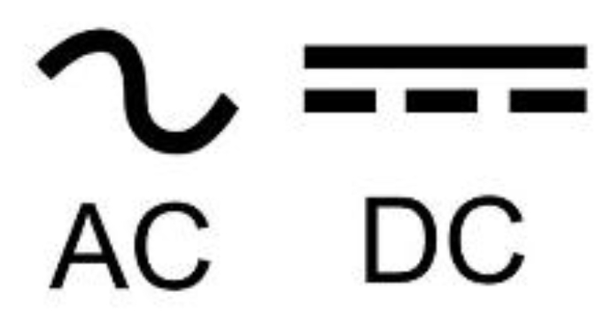


We will use a fuse of 20A. This is the same as the previous example. The difference here is the voltage. The voltage will be 122V DC to the charge controller:


This is over the max allowed input voltage of the previous charge controller. We need to use a charge controller with a max input voltage of 150VDC. We will use the Epever XTRA series 40A.
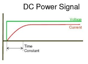
Next, we will calculate the wire. We assume the charge controller's wire length is 20ft or 6 meters. If we plug this data in a voltage drop calculator at 122VDC, we become 16AWG or 1.5mm² with an acceptable voltage drop of 2.1%.


Link to the calculator:

https://cleversolarpower.com/voltagedropcalculator


F2: The following wire goes from the charge controller to the busbar. The maximum current that can go through this wire is:


We will use a safety factor of 1.25:


This is slightly above the current output of the 40Amp controller. This is relatively small, so it doesn’t need to be upgraded. The charge controller has a limited output of 40A. The manufacturer says that we need a safety factor of 1.25 times this current. . A wire suited for 50A is a 6AWG or 16mm². Since the maximum current from the solar panels will be 41.66A, we will use a 50A fuse.
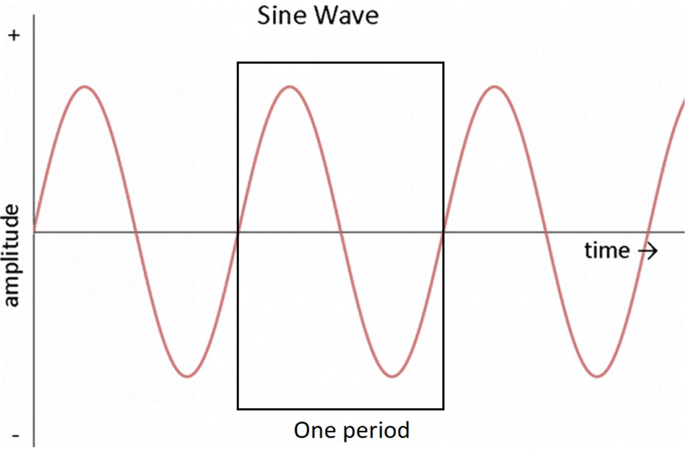
 

F3: This wire goes from the DC busbar to the inverter. This wire needs to be kept short. Because we have a 24V system, we have a maximum current of:
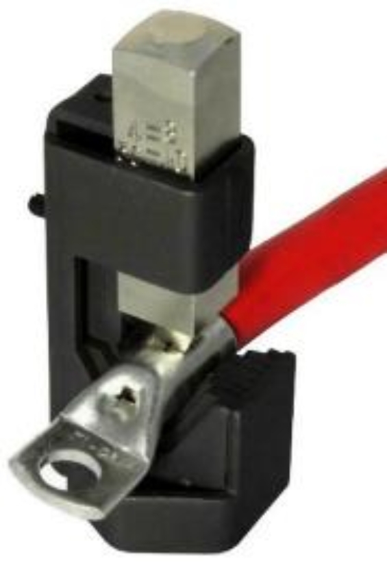


We need a safety margin of 1.25, so the current becomes 52A. A wire rated for 60A is 6AWG or 16mm². Because the maximum current through this wire is 52A, we will use a 60A fuse.

F4: This wire goes from the DC busbar to the DC fuse box. The max power that will be used is 250W. This gives us a current of:


Applying a safety factor of 1.25, we become 13A. A wire which can carry 13A is 14AWG or 2.5mm². We will fuse this wire with a 15A fuse.


F5: This wire goes from the battery to the DC busbar. This will be the wire with the most amount of current in the system. If we add up all the power in the system we become 1250W. To get the total current, we divide the power by the battery's voltage.
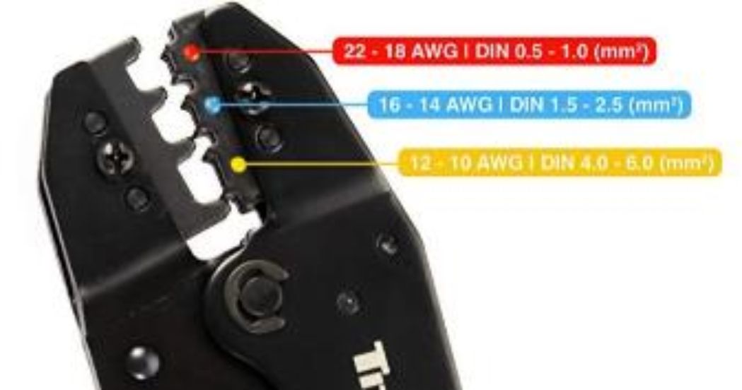



With a safety factor of 1.25, we become 65A. A wire that can carry 65Amps is 6AWG or 16mm². We need to keep this wire as short as possible to minimize voltage drop. Since the max current in this wire is 65A, we can use a 70A fuse.

48V 3kW inverter with 3kW of solar

Diagram  Description automatically generated


This system could be for a small to medium off-grid homestead. We have chosen nine solar panels from Rich Solar. These panels have the following specifications:


  • Maximum Power(Pmax): 335W
  • Open Circuit Voltage(Voc): 41.6V
  • Short Circuit Current(Isc): 10.4A
  • Max Series Fuse Rating: 20A

We connect these solar panels to the off-grid inverter from EG4. This is a 3kW hybrid inverter that includes an MPPT charge controller with a max input voltage of 450VDC. We can connect all our solar panels in series to this hybrid inverter.
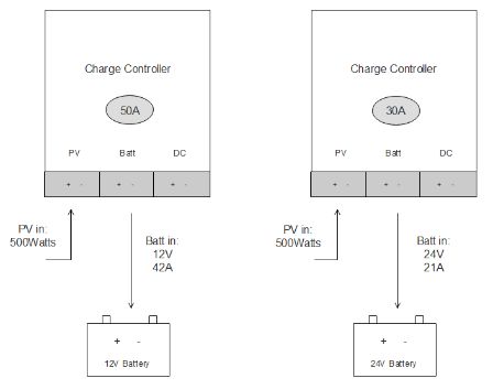
 

Connecting this hybrid inverter to the utility or a generator is possible.


Lastly, we have chosen two LiFePo4 server rack batteries. These can be from EG4, SOK or others. We have selected two pieces at 48V and 100Ah. They have a combined 10kWh of storage.


The 9 solar panels have a combined power output of 3015W. If you live in a place with three sun hours per day, you can charge these batteries in one day.


The wire size from the solar panels to the hybrid inverter will have a maximum current of 10.4A. We need to apply the safety factor of 1.56.


The solar panel voltage will be:


If we assume the distance from the solar array to the inverter is 50ft or 15m, we can wire with 14AWG or 2.5mm². This is because we have wired our panels in series where the voltage gets added up, but the current stays the same.


The fuse for this wire (F1) should be 20A because this is the fuse size that is recommended on the solar panel specifications. There will also be a solar disconnect switch which is rated for 500VDC.


The following wire goes from the hybrid inverter to the server rack batteries. The batteries are wired in parallel. The main positive comes from battery one, and the main negative comes from battery two. This is to ensure the current is shared between the two batteries and one doesn’t work more than the other. A battery busbar will be a good option if you have more than two batteries.

 

The maximum amount of current through this wire is:


A wire which can carry this current is 4AWG or 25mm². We need to use a class-T fuse that can disconnect a high current short circuit (200kA from Littelfuse). A class-T fuse of 100A will keep this wire safe from overcurrent. We can also use a ceramic fuse with a fuse holder on a DIN rail.

48V 5kW inverter 9kW of solar


This system is for a large off-grid homestead or a house. We have chosen 28 solar panels from Rich Solar. These panels have the following specifications:


  • Maximum Power(Pmax): 335W
  • Open Circuit Voltage(Voc): 41.6V
  • Short Circuit Current(Isc): 10.4A
  • Max Series Fuse Rating: 20A

Instead of using an all-in-one hybrid inverter, we will choose separate components this time. We will use two 450V/100A charge controllers and one Victron Multiplus II 5kW inverter. You can integrate this inverter with your home. When there is a blackout, you still have power for your critical loads.


You can add more units in parallel if you need more inverter power. We will use a 48V 500Ah server rack battery. This is 25kWh of storage and will be charged in one day by the solar panels if you have 3 sun hours.


Now we need to calculate the voltage at the input of the charge controllers. This may not exceed 450V.


The solar panels will be divided into 4 parallel arrays with 7 panels in series (7S4P). This will give us a total combined power of 9380W of solar at STC.


The current through this wire is just like the previous system. As the solar panel manufacturer recommended, we need to fuse every series string with an inline MC-4 fuse of 20A (F1,2,3,4).

Let’s say the length of the wire is 100ft or 30 meters. Then we need a 14AWG or 2.5mm² wire.


Link to calculator:

https://cleversolarpower.com/voltagedropcalculator


The following wire will go from the charge controller to the busbar. The maximum current through the charge controller is 100A. We need to apply the safety factor:


We need a 1AWG or 50mm² wire from the charge controller to the busbar. The wire will be fused at 150A (F5,6). We need to double this setup because we have two charge controllers.


Our load will be attached to the inverter, and the maximum power the inverter will draw is 5kW.


The power from the charge controllers will be higher than the potential current drawn from the inverter.


We can use the same wire from the charge controller to the busbar. But we need to double them up. This means that there will be two 1AWG or 50mm² cables going from the busbar to the battery busbar, each fused at 150A (F7).


We already calculated the current for the 5kw inverter, which is 130A. We can use a 150A fuse from the busbar to the inverter (F8). We can use 1AWG or 50mm². Alternatively, we can use two 4AWG or 25mm² wires. The inverter comes with double connection points.


Recommended Brands


The following brands are personal recommendations. These companies have a good reputation within the solar community. The brands are listed in no particular order.


To see a list of up-to-date components, refer to my website at: cleversolarpower.com

Epever

Epever is a Chinese company established in Shenzhen that manufactures charge controllers and off-grid inverters. Available charge controllers can either be MPPT or PWM based, and their outputs can go from 10A to 60A. The brand also makes pure sine wave inverters.

Rich Solar

Rich Solar is a popular American-based company dedicated to supplying off-grid solar equipment for RVs, agriculture, housing, marine, light, and heavy industrial equipment. The brand manufactures solar panels (both rigid and flexible), charge controllers (both MPPT and PWM), inverters, solar lights, accessories and sells pre-assembled solar power kits.

Batteriesplus

Batteriesplus is another valuable brand with over 20 years in the market that can be used if you are looking for reliable sealed lead-acid RV batteries.

Victron Energy

Victron Energy is a company from the Netherlands that is one of the top brands available in the market for off-grid applications and commercial systems. This brand offers multiple component options such as inverters, lithium batteries, charge controllers, solar panels, battery isolators, battery combiners, auto-transformers, and much more.

Renogy

Probably the most valuable option in the off-grid market for RVs is Renogy. An American-based company that manufactures charge controllers (PWM and MPPT), pure sine wave inverters, deep cycle, lithium-ion phosphate batteries, and solar panels (flexible and rigid). Be careful with their lithium batteries. They cannot be put into series.

AltE Store

This is a reputable online store for solar products. You can find anything from solar panels, well pumps, charge controllers, inverters, batteries, just to name a few.

Battleborn

Battleborn is an American-based company that sells lithium batteries. These batteries are of great quality and have outstanding support.

Growatt

Growatt is a Chinese brand with products for grid-tied and off-grid solar power applications. Many people using growatt’s all-in-one inverter or hybrid inverters are happy with their purchase. They have many service centers in the US and Europe.

MPP Solar

MPP solar is a company from Taiwan that is specialized in creating hybrid inverters. Many other Chinese brands produce knock-offs from this brand. These knock-off brands look similar but use cheaper components and don’t have support.

Your local hardware store

You should go to your local hardware store for items such as crimp connectors or wires. These items are of good quality, with safety certification. If you buy from Amazon or eBay, you do not know that you are getting good materials.

Conclusion


This book has the sole purpose of providing you with information to establish your solar power system.


I hope this book has accomplished that purpose.


Never forget that the safety of you and the people around you should be your priority. Take extreme care when working with tools that are not insulated.


Enjoy the process of making your solar system from scratch. Contact a licensed electrician for more information if you are unsure about certain things. You can also reach me on my website cleversolarpower.com


To view the color images and schematics on the website, visit:

https://cleversolarpower.com/offgridsolarbook and use the following password: offgrid


Take care,

Nick